
Summary of Contents for Matelect DCM-2
- Page 1 MATELECT DCPD Crack Growth Monitor TYPE DCM-2 INSTRUCTION MANUAL Version 32, February 2018...
- Page 2 MATELECT DCM-2 INSTRUCTION MANUAL...
- Page 3 The firmware is user upgradeable and new firmware can be provided on CD, or by email from Matelect and “flashed” into the DCM-2 by the end-user simply by using a PC and a serial cable.
- Page 4 Therefore, PLEASE ENSURE that the instrument is earthed to the mains earth via the IEC connector. In addition to the fuse that may be present in the mains plug (e.g. UK versions), the DCM-2 is fitted with an equipment fuse for protection. The fuse is located in the IEC input socket on the rear panel of the DCM-2 .
-
Page 5: Table Of Contents
Thermoelectric EMF’s....................... 26 Noise............................27 Other considerations ........................27 Setting up and doing a test ........................28 A basic fatigue test using the DCM-2 ..................28 Communications protocols ........................30 Specifications ............................32 Document History ..........................33 Modified Advanced Menu. Feb 2011 ....................33 Peripheral equipment .......................... - Page 6 MATELECT DCM-2 INSTRUCTION MANUAL...
- Page 7 The predecessor to the DCM-2 , the DCM-1, was produced to replace the ageing DC systems that were and are still common in laboratories throughout the world, with a modern, sophisticated yet easy to use instrument.
- Page 8 For now, the matter remains unresolved but for those researchers that prefer the concept of reversing- DCPD, the DCM-2 can be specified at the time of purchase (or retrofitted) with a reversing module. This works in harmony with the pulsed DCPD operation of the DCM-2 to produce the World’s first pulsed- reversing-DCPD instrument.
- Page 9 DCM-2 . In many cases, the last digits resolvable on the DCM-2 correspond to distances on the specimen of less than a grain size.
-
Page 10: Dcm-2 General Description & Setup
DCPD readings, the main unit also performs a normalisation calculation if the user has selected two-channel operation. Analogue outputs are provided at the rear of the DCM-2 so that the values of the specimen channel, the reference channel and the normalised DCPD value can be recorded via a computer (suitably equipped with an analogue to digital converter card) or a chart recorder. - Page 11 DCM-2 current I/O to specimen (2off 1 red, 1 black) Specimen to reference current lead mini 2 pin signal input DCM-2 preamplifier module to specimen connection (2off 1 blue, 1 orange) PC COM1 to DCM-2 RS232 socket Figure 2 Cables supplied with DCM-2...
-
Page 12: Front Panel Description
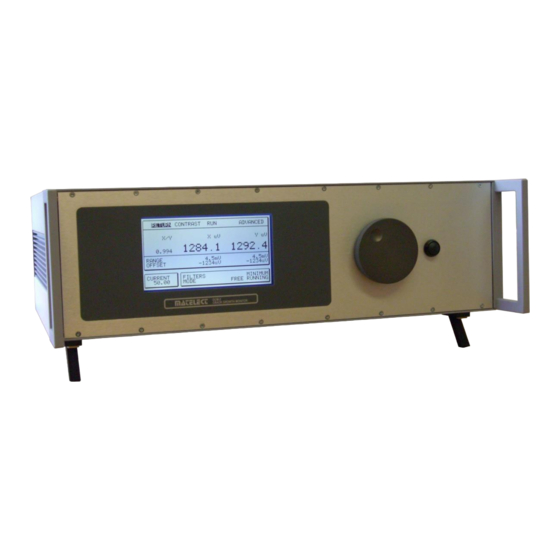
MATELECT DCM-2 INSTRUCTION MANUAL FRONT PANEL DESCRIPTION The front panel layout of the DCM-2 is shown below in Figure 3. The controls and menu functions of the unit are described fully in this section. Figure 3 The front panel of the DCM-2... -
Page 13: Front Panel Display
Run – this will initiate run mode. The unit will start to gather data, using the parameters, as displayed on screen. Please note that the DCM-2 will take a few cycles to stabilize; and it is best practice to allow the unit to stabilize for 15 minutes. -
Page 14: Range
DCM-2. In the unlikely event that after a few pulses the DCM-2 is still indicating a current less than that set by the user. It has most likely reached maximum drive capability; this is often referred to as voltage compliance. -
Page 15: Filter
If the user can not acquire the current they require they should contact Matelect for advice. When the current level is set, activated, and the DCM-2 unit is correctly pulsing, the front panel graphics screen will indicate each pulse with a small asterix (*) adjacent to the displayed value of the current. If a reversing module has been fitted, a minus signs (-) will appear next to the asterix, when the current is reversed with respect to its initial polarity. -
Page 16: Advanced Menu
Off Time In Seconds This defines the time the DCM-2 waits before starting to take the next set of readings. This is useful when a slow crack growth is being monitored, and the readings are like to be affected by the heating effects of the current. -
Page 17: Number Of Readings
This is also explained in greater detail on page 22. Scanner Voltage Channel When the SC1 module is fitted to the DCM-2 this menu option is user to adjust the selected channel on the voltage scanner during setup. -
Page 18: Rear Panel Description
MATELECT DCM-2 INSTRUCTION MANUAL REAR PANEL DESCRIPTION The rear panel of the DCM-2 is shown below. Located on this panel are the IEC mains inlet socket, the fan outlet grill, the current I/O sockets, the external I/O socket, RS232 socket, Load input, analogue outputs, and preamplifier inputs. -
Page 19: Iec Inlet Socket
DO NOT use a fuse of a higher rating as permanent damage may result to the DCM-2 . If the local mains plug also incorporates a fuse, then this should be of a similar rating to the fuse within the IEC socket. -
Page 20: Serial Data (Rs232) Output Socket
Matelect. With the addition of the usb port to the DCM-2 the RS232 input to the DCM-2 is disabled while a “live” usb cable is connected to the DCM- Load input Also referred to as the machine cycle input this BNC style connector allows the DCM-2 to be synchronised with an external signal as found on most testing machines. - Page 21 ‘CP210x USB to UART’ with a COM port number in brackets. It should be noted that connecting a “live” usb cable to the DCM-2 will disable any input from the RS232 port until the cable is removed.
-
Page 22: Advanced Usage And Advanced Menu
64 continuous readings. The current is then switched off and allowed to settle again for 20mS. The DCM-2 as before waits for a negative to positive zero crossover point in the mains cycle and takes 64 continuous readings again. -
Page 23: External Synchronisation Mode 130 - 500Hz
The current is then switched off and allowed to settle again for 20mS. The DCM-2 then waits for the same mains cycle point at which it took the first of the 64 ‘current on’ readings, and proceeds to take a single ‘off current’ reading. -
Page 24: Other Options
DCM-2 . Indeed when these values are adjusted from the Advanced Menu, a return to the Operating screen of the DCM-2 will reveal that the Filter setting is now “User Defined”. The Filter settings are simply default sub-sets of the combination of readings and samples that the unit is capable of achieving. - Page 25 If this is the case, then the unit should either be operated in monopolar mode or end-users can request a firmware update to the DCM-2 which will display the calculated average of the two polarities of DCPD, rather than the individual values, thus removing the...
-
Page 26: Making Connections To A Specimen
(see Fig 1). Users should always employ the standard cables as supplied by Matelect with the DCM-2 system. If the cables have had to be lengthened, please ensure that the same types of cables are used and that the connections to the DCM-2 are made correctly. -
Page 27: Noise
MATELECT DCM-2 INSTRUCTION MANUAL temperature change occurs between the two sets of readings. This is a fair assumption unless abnormally high rates of heating or cooling are occurring. Noise All cables leading from the specimens to the pre-amplifier should be shielded from stray EM radiation and as short as practicable. -
Page 28: Setting Up And Doing A Test
Providing the precautions and recommendations already described in this manual have been followed, no damage can be done to the DCM-2 by a non-standard combination of menu options, so the user should feel free to experiment with the parameters in order to achieve an optimum test result. - Page 29 The readings obtained should be similar to those observed during the set-up test. If they are not check the level of noise on the signal by observing the front panel readings. Also check the integrity of the connections and the isolation of the specimen. Contact Matelect for further advice if a problem remains.
-
Page 30: Communications Protocols
Parity = none Start bits =1 Data bits = 8 Stop bits = 1 Handshaking = xon/xoff There are options to configure the DCM-2 digital output to be the same as a DCM-1 or to be defined by the user. - Page 31 MATELECT DCM-2 INSTRUCTION MANUAL...
-
Page 32: Specifications
MATELECT DCM-2 INSTRUCTION MANUAL SPECIFICATIONS DCM-2 Model range. Option1 10A maximum current output. 10A maximum current output, with Advanced triggering Option2 Option3 10A maximum current output, with Advanced triggering, and 20 volt output supply Option4 50A maximum current output. 50A maximum current output, with Advanced triggering... -
Page 33: Document History
Midpoint of load swing This defines the midpoint of the load waveform the DCM-2 is expected to synchronize with, in volts. This is the point equal distance in potential between the maximum and minimum values and should not be confused with the mean load although in symmetrical waveforms this is true. - Page 34 Correction to Figure 1 to better describe the real world layout and match Figure 6 . Modifications to “Rear panel description” February 2014 Ver 25 Introduction of USB to the DCM-2. The manual was modified in the “Rear panel description” section to reflect this.
-
Page 35: Peripheral Equipment
PERIPHERAL EQUIPMENT SM1-HC & SM2-HC To increase the versatility of the DCM-2 crack growth monitor, Matelect has developed a new compact, modular signal and current multiplexing system designed to allow multi-point monitoring of specimens undergoing crack growth measurements. In its basic form the system is capable of measuring up to 4 signal points (reference plus specimen) simultaneously. - Page 36 MATELECT DCM-2 INSTRUCTION MANUAL SM1-HC AND SM2-HC SPECIFICATIONS SC1 MODULE SPECIFICATIONS Modes EXTernal (PC), MANual and AUTOmatic Capability 256 channels SM1-HC SPECIFICATIONS Type 4 channel DCPD voltage signal switching module Addresses 000000 to 111111 (Set via an Internal 6 way DIL switch)
-
Page 37: Warranty
REPAIR AND RECALIBRATION: Matelect Limited can repair and/or recalibrate instruments manufactured by it, after the warranty period has expired. If this service is required then please contact Matelect and we will be pleased to provide a quotation for the work necessary. - Page 38 MATELECT Telephone: +44 (0)1895 823334 Facsimile: +44 (0)1895 824300 E-mail: info@matelect.com...
Need help?
Do you have a question about the DCM-2 and is the answer not in the manual?
Questions and answers