Advertisement
Quick Links
2step Box: Instruction Manual
WARNING:
For off-road or closed course use ONLY. Use this product with GREAT
CAUTION. Misuse of this product can cause serious engine damage and
exhaust damage. ALPHAX takes no responsibility for the damage caused by
the misuse of this product
Note: 90 day warranty on manufacturing defects. Restrictions may apply.
Advertisement

Summary of Contents for ALPHAX 2step Box
- Page 1 For off-road or closed course use ONLY. Use this product with GREAT CAUTION. Misuse of this product can cause serious engine damage and exhaust damage. ALPHAX takes no responsibility for the damage caused by the misuse of this product Note: 90 day warranty on manufacturing defects. Restrictions may apply.
- Page 2 It is your duty to consult an electrical diagram of your brand and vehicle model to identify the correct cables for the installation. 4) If the application for which you purchased the 2step box falls out of the diagrams in this manual, you should use the universal diagrams for single or multiple coil and consult an automotive technician to complete a suitable installation.
- Page 3 Symbols & Terms Switch How it looks Symbol How it connects Ground 2step signal Ground How it connects Symbol MPI: Cars with multi point injectors near intake valve. GDI: Cars with gasoline direct injection or injectors inside the combustion chamber.
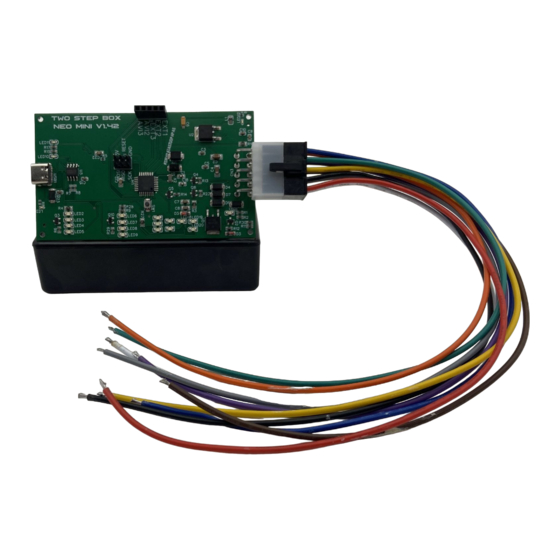
- Page 4 Wire name and color 12V (Red) Coil (Orange) 2step signal (Green) ALPHAX 2STEP BOX RPM (Grey) Ground (Black) Toyota/Lexus IGF (Pink) Warning: If this product is not installed according to the instructions or wiring diagram for the specific application, warranty will be void automatically.
- Page 5 The harness side of the original wire connects to the “12V” wire (red). Coil Signal wire Coil Position sensor of exhaust camshaft 12V wire White Coil Coil wire ALPHAX 2STEP BOX RPM cable 2step signal wire Ground wire Switch Ground...
- Page 6 “12V” wire (red). Coil Coil 12V wire Coil Coil wire RPM wire ALPHAX 2STEP BOX 2step wire Ground wire Switch WARNING: If product is not installed according to the instructions or wiring diagram for the specific application, warranty will be Ground...
- Page 7 MUST BE LEFT UNCONNECTED and away from Coil any piece of metal to prevent short circuits. The other side of the wire (the harness side) connects to the IGF wire (pink wire) of the 2step box. Coil Coil ALPHAX...
- Page 8 “12V” wire (red) Coil signal wire Coil 12V wire Coil Coil wire ALPHAX 2STEP BOX RPM wire 2step signal wire Ground wire Switch WARNING: If product is not installed according to the instructions or wiring diagram for the specific application, warranty will be Ground/Tierra void automatically.
- Page 9 Coil 12V wire Coil wire RPM wire ALPHAX 2STEP BOX Cable de señal de 2step Coil wire Switch WARNING: If product is not installed according to the instructions or wiring diagram for the specific application, warranty will be void automatically.
- Page 10 Vehicles with MSD systems...
- Page 11 Vehicles that use the white cable of the MSD (see photo on this page) to pulse the MSD see the diagram with the instructions on the next page.
- Page 12 Cut switched 12V wire of the MSD, this is the thin red wire. The MSD side of the wire connects to the “coil” wire (orange) of the 2step box. The other side of the wire, the harness side, connects to the “12V” wire (red) of the 2step box.
- Page 13 Vehicles that use the green and violet cables of the MSD (see photo on this page) to pulse the MSD, see the diagram with the instructions on the next page.
- Page 14 Cut switched 12V wire of the MSD, this is the thin red wire. The Battery 12V MSD side of the wire connects to the “coil” wire (orange) of the 2step box. The other side of the wire, the harness side, connects to the “12V” wire (red) of the 2step box. Coil...
-
Page 15: Basic Setting
Basic Setting The 2step box contains the basic parameters to be able to make the effects in any car. It contains a 10-position wheel (photo) in which you can choose between making cuts fast at 7 different rpm and slow cuts at 3 different rpm. If you want to change the parameters in any... - Page 16 Programming by USB...
- Page 17 Install USB to serial driver: CH340 Driver Download CH340 driver installer...
- Page 18 Install Communication Software: Putty Download Putty installer...
- Page 19 Click if you would like a Desktop Shortcut...
- Page 20 Connecting the 2Step Box to your laptop Step 1: Open Device Manager Step 2: Connect 2Step Box to laptop with USB cable Step 3: Identify COM Port Step 4: Open Communication Software Putty Step 5: Select “Serial” under “Connection Type”. Set COM Port number and set serial port Speed to 115200.
- Page 21 Tuning the 2Step Box Once the serial communication is open, the box will send the message “Box Ready”. Hit the “W” key on your keyboard which will activate the “write” function. This function sets a desired “cut period” in milliseconds, at a desired “cut RPM” and will save it into a desired switch position in the 10 position switch.
- Page 22 Tuning the 2Step Box The 2Step Box comes programmed to receive a ground signal from a “normally open” switch. In order to change the signal logic to use normally closed switches, hit the “I” key to invert the signal logic in the box.
Need help?
Do you have a question about the 2step Box and is the answer not in the manual?
Questions and answers