Table of Contents
Advertisement
Quick Links
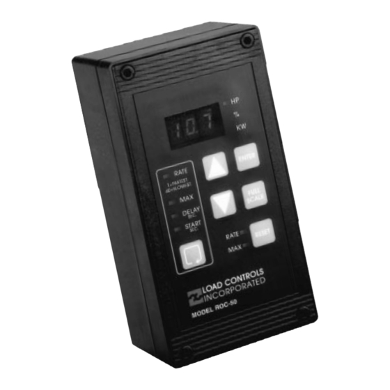
ROC-50 RATE OF CHANGE LOAD CONTROL
ROC-50 RATE OF CHANGE LOAD CONTROL
INSTALLATION, SET UP AND ADJUSTMENT
INST ALLATION, SET UP AND ADJUSTMENT
L OAD CONTROLS
INCORPORATED
The Model ROC-50 monitors the true power going to a motor.
By sensing power (volts x amps x power factor) rather than just
amps, there is much greater sensitivity. It has two adjustable set
points.
Rate - Limits sudden increases in load regardless of total load.
Max - Limits the total load.
MOUNTING
MOUNTING
Wiring is done to un-pluggable terminal strips on the rear of the unit.
Three ways to mount:
•
O n door or raceway - use cutout template
•
Panel Mount - use template + optional Bezel Kit (No Charge)
•
O n wall - on standard outdoor junction box + optional
O utlet Box Adapter (No Charge)
VOLTAGE
VOL T AGE
120 volts AC is taken from two of the phases. If the motor
starter already has a 120-volt control transformer with 10VA
of free capacity, it can be used. O therwise, install a separate
transformer. It is okay if the secondary is grounded.
BE SURE TO NO TE WHICH TWO PHASES SUPPL Y THE
TRANSFO RMER.
In 120/ 208V three-phase system, the 120V MUST come from a
transformer connected to two of the phases. The 120V phase to
ground voltage cannot be used.
CURRENT
CURRENT
The current signal is taken from the REMAINING phase.
This current sample passes through the Range Finder Toroid.
It is VERY IMPO RTANT that the current signal comes from the phase
that IS NO T supplying the 120V control transformer. Be extra careful
when the machine has reversing starters or multi-speed windings. If a
wrong phase is used the control will either:
•
Work backwards
If you are using a variable frequency drive, use a different control.
Call LOAD CO NTRO LS, INC. for help.
Call LOAD CONTROLS, INC for help.
•
Have reduced sensitivity
Advertisement
Table of Contents

Summary of Contents for LOAD CONTROLS ROC-50
- Page 1 INSTALLATION, SET UP AND ADJUSTMENT INST ALLATION, SET UP AND ADJUSTMENT The Model ROC-50 monitors the true power going to a motor. By sensing power (volts x amps x power factor) rather than just amps, there is much greater sensitivity. It has two adjustable set points.
- Page 2 RELAY OUTPUTS — POWER ON, NOT TRIPPED REMOTE RESET RATE TRIP TRIP REMOTE RATE 4-20 RANGE FINDER MA OUTPUT TOROID CURRENT FROM REMAINING PHASE VOLTAGE TRANSFORMER WITH 120V SECONDARY FULL SCALE CAPACITY AT 460 VOL TS FULL SCALE CAPACITY AT 460 VOLTS The Range Finder Toroid has six motor size choices.
- Page 3 A Current Transformer is used to reduce the primary current. The 5-amp secondary passes through the Toroid. THE R OC -50 POWERS THE 4-20 MA SIGNAL THE ROC-50 POWERS THE 4-20MA SIGNAL. DON’T USE AN EXTERNAL DC POWER SUPPLY! DON’T USE AN EXTERNAL DC POWER SUPPL Y.
- Page 4 FRONT PANEL SET-UP TIPS TO SET FULL SCALE FRONT P ANEL SET-UP TIPS • After hook-up, find your HP, KW or % from the chart None of the settings will be changed until you hold ï After hook-up, f ind your HP , KW or % fr om the chart. 1) None of t he settings will be changed until you hold down and the fast blinking stops.
Need help?
Do you have a question about the ROC-50 and is the answer not in the manual?
Questions and answers