
Summary of Contents for Hans Turck BL20-ECO
- Page 1 Your Global Automation Partner BL20-E-GW-CO ECO Gateway for CANopen Instructions for Use...
- Page 2 Hans Turck GmbH & Co. KG | T +49 208 4952-0 | F +49 208 4952-264 | more@turck.com | www.turck.com...
-
Page 3: Table Of Contents
Table of Contents About These Instructions Target groups Documentation concept Explanation of symbols used 1.3.1 Additional documents Feedback about these instructions Notes on the Product Product identification Scope of delivery Legal requirements Manufacturer and service For Your Safety Intended use General safety instructions Short Description of CANopen CANopen... - Page 4 8.1.3 Lightning protection 8.1.4 Transmission cable Potential relationships 8.2.1 General 8.2.2 Potential-free installation Electromagnetic compatibility (EMC) 8.3.1 Ensuring electromagnetic compatibility Hans Turck GmbH & Co. KG | T +49 208 4952-0 | F +49 208 4952-264 | more@turck.com | www.turck.com...
- Page 5 8.3.2 Grounding of inactive metal components 8.3.3 PE connection 8.3.4 Earth-free operation 8.3.5 Protection against high frequency interference signals 8.3.6 Mounting rails 8.3.7 EMC compliant cabinet installation Shielding of cables 8.4.1 Potential compensation 8.4.2 Switching inductive loads 8.4.3 Protection against Electrostatic Discharge (ESD) BL20-Approvals for Zone 2/Division 2 2020/09...
- Page 6 Hans Turck GmbH & Co. KG | T +49 208 4952-0 | F +49 208 4952-264 | more@turck.com | www.turck.com...
-
Page 7: About These Instructions
Documentation concept This manual contains all information about the CANopen-Gateway of the product line BL20-ECO (BL20-E-GW-CO). The following chapter contain a short BL20-description, a description of the used field bus system,... -
Page 8: Explanation Of Symbols Used
Hans Turck GmbH & Co. KG | T +49 208 4952-0 | F +49 208 4952-264 | more@turck.com | www.turck.com... -
Page 9: Notes On The Product
2014/30/EU (electromagnetic compatibility) 2011/65/EU (RoHS Directive) Manufacturer and service Hans Turck GmbH & Co. KG Witzlebenstraße 7 45472 Muelheim an der Ruhr Germany Turck supports you with your projects, from initial analysis to the commissioning of your applica- tion. - Page 10 Notes on the Product Hans Turck GmbH & Co. KG | T +49 208 4952-0 | F +49 208 4952-264 | more@turck.com | www.turck.com...
-
Page 11: For Your Safety
For Your Safety The product is designed according to state-of-the-art technology. However, residual risks still exist. Observe the following warnings and safety notices to prevent damage to persons and property. Turck accepts no liability for damage caused by failure to observe these warning and safety notices. Intended use The devices are only intended for use in industrial applications. - Page 12 For Your Safety Hans Turck GmbH & Co. KG | T +49 208 4952-0 | F +49 208 4952-264 | more@turck.com | www.turck.com...
-
Page 13: Short Description Of Canopen
Short Description of CANopen CANopen The following description of CANopen is an excerpt from the homepage of CiA (CAN in Automa- tion), the international users’ and manufacturers’ organization for CAN. CANopen is an open, non-proprietary network protocol. It consists of a profile family, based on a communication profile and several device profiles.i The CANopen communication profile is stan- dardized as CiA DS-301 (Application Layer and Communication Profile). -
Page 14: Service Data Objects (Sdos)
Sync message received: Hans Turck GmbH & Co. KG | T +49 208 4952-0 | F +49 208 4952-264 | more@turck.com | www.turck.com... - Page 15 PDO transmissions „Event-“ or „timer-driven“: An event (specified in the device profile) triggers message transmission. An elapsed timer addi- tionally triggers the periodically transmitting of PDO-messages, even if no event has occurred. Remotely requested: Another device may initiate the transmission of an asynchronous PDO by sending a remote trans- ...
-
Page 16: Bl20 And Canopen
The EDS file lists all necessary Objects with their corresponding Sub-indices and the matching entries. The latest version of a particular EDS file can be downloaded directly from the Turck homepage www.turck.com. Hans Turck GmbH & Co. KG | T +49 208 4952-0 | F +49 208 4952-264 | more@turck.com | www.turck.com... -
Page 17: Eco Gateway For Canopen
Eco Gateway for CANopen Introduction This chapter contains a description of BL20-E-CO-gateways for the standardized fieldbus CANopen. The chapter is divided up as follows: a description of functions, general and specific technical data, a description of addressing and status displays. 5.1.1 Function The BL20 gateways enable BL20 modules to operate on CANopen. -
Page 18: Technical Data
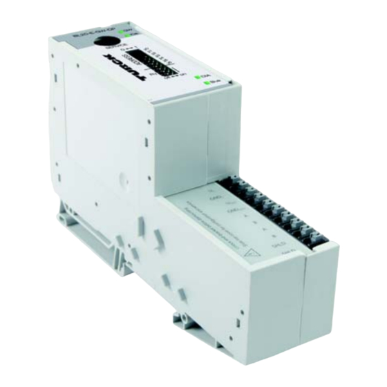
F DIP-switch for terminating resistor G LEDs for CANopen H Push-In for field supply I Push-In terminals for system supply J CANopen, Push-In terminals Hans Turck GmbH & Co. KG | T +49 208 4952-0 | F +49 208 4952-264 | more@turck.com | www.turck.com... -
Page 19: General Technical Data Of A Station
Structure of a BL20-ECO gateway Field bus Service Controller External Module bus (external) interface (internal) – internal External ROM-Flash – WDG – RTC Fig. 2: Structure of a BL20-E-GW-CO 5.2.1 General technical data of a station WARNING Defective power supply unit Danger to life due to dangerous voltages on touchable parts †... - Page 20 10 V/m EN 61000-4-3 and ENV 50 204 Conducted interferences induced by HF fields 10 V according to EN 61000-4-6 Hans Turck GmbH & Co. KG | T +49 208 4952-0 | F +49 208 4952-264 | more@turck.com | www.turck.com...
- Page 21 Technical Data Fast transients (Burst) according to EN 61000-4-4 Emitted interference according to EN 50081-2 According to EN 55 55011 Class A, Group 1 (industry) Using the device in residential areas can cause distur- bances. In this case, additional measures to suppress the disturbance are necessary.
-
Page 22: Technical Data For The Push-In Tension Clamp Terminals
/0.0008…0.0023 inch /25…16 AWG "f” with ferrules according to 0.25…1.5 mm /0.0004…0.0023 inch /30…16 AWG DIN 46228/1 (ferrules crimped gas-tight) Hans Turck GmbH & Co. KG | T +49 208 4952-0 | F +49 208 4952-264 | more@turck.com | www.turck.com... -
Page 23: Connection Options At The Gateway
Connection options at the gateway The fieldbus connection as well as the power supply connection are realized via Push-in tension clamp terminals. GND L U SYS GND SYS CAN_H CAN_L CAN_H CAN_L CAN GND CAN GND Fig. 3: Push-in tension clamp terminals at the gateway NOTE The minimum temperature rating of the cable to be connected to the field wiring termi- nals must be min. -
Page 24: Fieldbus Connection Via Push-In Tension Clamp Terminals
Fig. 4: PS/2 male connector on the connection cable to the gateway (top view) Fig. 5: 9-pole SUB-D female connector on the cable for connecting to PC (top view) Hans Turck GmbH & Co. KG | T +49 208 4952-0 | F +49 208 4952-264 | more@turck.com | www.turck.com... - Page 25 BL20 gateway SUB-D interface at the PC PS/2 female connector DTR, DSR 4, 6 DATA – – n.c. (DATA2) +5 V n.c. (CLK2) 2020/09...
-
Page 26: Setting The Node Id
Bus address 38 = 0×26 = 100110 Fig. 7: Bus address 38 The internal module bus does not require any addressing. Hans Turck GmbH & Co. KG | T +49 208 4952-0 | F +49 208 4952-264 | more@turck.com | www.turck.com... -
Page 27: Setting The Bit Rate
Setting the bit rate The gateway BL20-E-GW-CO offers 3 DIP switches for setting the bit rate (BR). Fig. 8: DIP switches for setting the bit rate DIP-switch Bit rate autobaud 20 kbps 50 kbps 125 kbps 250 kbps 500 kbps 800 kbps 1 Mbps 5.5.1... -
Page 28: Activation Of The Terminating Resistor
If the new configuration stored to the gateway does not match the old configuration, all CANopen-parameters are set to their default values. Therefore it is necessary, to reload the whole station parameterization. Hans Turck GmbH & Co. KG | T +49 208 4952-0 | F +49 208 4952-264 | more@turck.com | www.turck.com... -
Page 29: Status Indicators/Diagnostic Messages
Status indicators/diagnostic messages The gateway transmits the following diagnostics: the status of the BL20 station, the communication via the internal module bus, the communication to CANopen and the status of the gateway. Diagnostics messages are indicated in two different ways: via the LEDs ... - Page 30 Set the correct Node-ID with the DIP alternately, 4 Hz switches (1 to 63) Red flickering, Autobaud function active alternately, 10 Hz Hans Turck GmbH & Co. KG | T +49 208 4952-0 | F +49 208 4952-264 | more@turck.com | www.turck.com...
-
Page 31: Bl20 - Communication In Canopen
BL20 - Communication in CANopen NOTE The CANopen-description for BL20 can be found in a separate manual ”BL×× CANopen- object register“ D301230 under www.turck.de. 2020/09... - Page 32 BL20 - Communication in CANopen Hans Turck GmbH & Co. KG | T +49 208 4952-0 | F +49 208 4952-264 | more@turck.com | www.turck.com...
-
Page 33: Guidelines For Station Planning
Guidelines for Station Planning Random module arrangement The arrangement of the I/O-modules within a BL20 station can basically be chosen at will. Nevertheless, it can be useful with some applications to group certain modules together. NOTE A mixed usage of gateways of the BL20 ECO and the BL20 standard product line and I/O modules of both product lines (base modules with tension clamp terminals) is possible without any problems. -
Page 34: Maximum System Extension
15 mA BL20-E-16DI-24VDC-P 15 mA BL20-16DI-24VDC-P 45 mA BL20-32DI-24VDC-P 30 mA BL20-1AI-I(0/4...20MA) 41 mA BL20-2AI-I(0/4...20MA) 35 mA BL20-1AI-U(-10/0...+10VDC) 41 mA Hans Turck GmbH & Co. KG | T +49 208 4952-0 | F +49 208 4952-264 | more@turck.com | www.turck.com... - Page 35 Module No. of Nominal current consumption at communication bytes the module bus BL20-2AI-U(-10/0...+10VDC) 35 mA BL20-2AI-PT/NI-2/3 45 mA BL20-2AI-THERMO-PI 45 mA BL20-4AI-U/I 30 mA BL20-2DO-24VDC-0.5A-P 32 mA BL20-2DO-24VDC-0.5A-N 32 mA BL20-2DO-24VDC-2A-P 33 mA BL20-2DO-120/230VAC-0.5A 35 mA BL20-4DO-24VDC-0.5A-P 30 mA BL20-E-8DO-24VDC-0.5A-P 15 mA BL20-E-16DO-24VDC-0.5A-P 25 mA...
-
Page 36: Power Supply
Ensure that the correct base modules are planned for when using Bus Refreshing modules. NOTE The system can be supplied with power independent of the potential group formation. Hans Turck GmbH & Co. KG | T +49 208 4952-0 | F +49 208 4952-264 | more@turck.com | www.turck.com... -
Page 37: C-Rail (Cross Connection)
When using a digital input module for 120/230 V AC, it should be ensured that a potential group is created in conjunction with the Power Feeding module BL20-PF-120/230VAC-D. NOTICE Common potential of 24 VDC and 230 VAC field supply Destruction of electronic †... - Page 38 Only then can the C-rail serve as PE again. Hans Turck GmbH & Co. KG | T +49 208 4952-0 | F +49 208 4952-264 | more@turck.com | www.turck.com...
-
Page 39: Direct Wiring Of Relay Modules
8 DI 2 DO ECO 2 DO 2 DI BL20-E-GW-CO SERVICE terminal GND L U SYS GND SYS CAN_H CAN_L CAN_H CAN_L CAN GND CAN GND C-rail (PE) C-rail (24 V DC) SBBC SBBC SBCS SBCS SBCS SBCS Abb. 5: Using the C-rail as protective earth and for the power supply with relay modules Cross-connecting relay module roots is achieved by the use of jumpers. -
Page 40: Plugging And Pulling Electronics Modules
Damage of the firmware † Disconnect the station from the modules bus before the download. † Disconnect the field side. Hans Turck GmbH & Co. KG | T +49 208 4952-0 | F +49 208 4952-264 | more@turck.com | www.turck.com... -
Page 41: Guidelines For Electrical Installation
Guidelines for Electrical Installation General notes 8.1.1 General Cables should be grouped together, for example: signal cables, data cables, heavy current cables, power supply cables. Heavy current cables and signal or data cables should always be routed in separate cable ducts or bundles. -
Page 42: Lightning Protection
Turck offers a variety of cable types for field bus lines as pre-molded or bulk cables with different connectors. The ordering information on the available cable types can be taken from the BL20-catalog. Hans Turck GmbH & Co. KG | T +49 208 4952-0 | F +49 208 4952-264 | more@turck.com | www.turck.com... -
Page 43: Potential Relationships
Potential relationships 8.2.1 General The potential relationship of a CANopen system realized with BL20 modules is characterized by the following: The system supply of gateway and I/O-modules as well as the field supply are realized via one power feed at the gateway. All BL20 modules (gateway, Power Feeding and I/O-modules), are connected capacitively via ... -
Page 44: Electromagnetic Compatibility (Emc)
A central connection must be established between ground and PE connection (protective earth). 8.3.4 Earth-free operation Observe all relevant safety regulations when operating an earth-free system. Hans Turck GmbH & Co. KG | T +49 208 4952-0 | F +49 208 4952-264 | more@turck.com | www.turck.com... -
Page 45: Protection Against High Frequency Interference Signals
8.3.5 Protection against high frequency interference signals In order to comply with radiation limit values in accordance with EN 55 011/2 000, the supply lines for supplying the gateway with power are to be fed through a ferrite ring (PS416-ZBX-405). This is to be placed immediately next to the connection terminals. -
Page 46: Emc Compliant Cabinet Installation
E Protective conductor system cable (grounding point) The cable must be connected over a large surface area with the protective conductor system. Hans Turck GmbH & Co. KG | T +49 208 4952-0 | F +49 208 4952-264 | more@turck.com | www.turck.com... -
Page 47: Shielding Of Cables
Shielding of cables Shielding is used to prevent interference from voltages and the radiation of interference fields by cables. Therefore, use only shielded cables with shielding braids made from good conducting mate- rials (copper or aluminum) with a minimum degree of coverage of 80%. The cable shield should always be connected to both sides of the respective reference potential (if no exception is made, for example, such as high-resistant, symmetrical, analog signal cables). -
Page 48: Potential Compensation
The compensation cable must be connected to the protective conductor over a large surface area and must be protected against corrosion. Hans Turck GmbH & Co. KG | T +49 208 4952-0 | F +49 208 4952-264 | more@turck.com | www.turck.com... -
Page 49: Switching Inductive Loads
Compensation cables and data cables should be routed as close together as possible, meaning the enclosed area should be kept as small as possible. Potenzialausgleich Abb. 5: Potential compensation Between switch cabinets 8.4.2 Switching inductive loads In the case of inductive loads, a protective circuit on the load is recommended. ... - Page 50 Guidelines for Electrical Installation Hans Turck GmbH & Co. KG | T +49 208 4952-0 | F +49 208 4952-264 | more@turck.com | www.turck.com...
-
Page 51: Bl20-Approvals For Zone 2/Division
BL20-Approvals for Zone 2/Division 2 NOTE The Zone 2 – approval certificates for BL20 can be found in a separate manual for approv- D301255 under www.turck.de. 2020/09... - Page 52 BL20-Approvals for Zone 2/Division 2 Hans Turck GmbH & Co. KG | T +49 208 4952-0 | F +49 208 4952-264 | more@turck.com | www.turck.com...
- Page 53 Over 30 subsidiaries and over 60 representations worldwide! D301108 | 2020/09 *D301108* www.turck.com...
Need help?
Do you have a question about the BL20-ECO and is the answer not in the manual?
Questions and answers