Table of Contents
Advertisement
Quick Links
Advertisement
Table of Contents

Summary of Contents for Aerosol Magee Scientific Aethalometer AE33
- Page 1 Aethalometer Model AE33 Aethalometer Model AE33 ® Service Manual Version 1.0 October 2020 Aerosol d.o.o., Ljubljana, Slovenia _______________________________________________________________________________________________________ Service manual – Ver. 1.0 October 2020 1/60...
- Page 2 Aethalometer Model AE33 Aethalometer® Model AE33 Service Manual Version 1.0, October 2020 Applicable for Magee Scientific Aethalometer® Model AE33 Copyright 2020 Aerosol d.o.o. Magee Scientific Aethalometer® Service Manual. All Rights Reserved. Aerosol d.o.o. Kamniška 39A SI-1000 Ljubljana Slovenia, EU tel: +386 1 4391 700 fax: +386 59 191 221 www.aerosol.eu...
-
Page 3: Table Of Contents
Aethalometer Model AE33 TABLE OF CONTENTS GENERAL INFORMATION ....................5 SAFETY NOTES AND LABELS ..................6 SERVICE PROCEDURES ON MAIN PARTS ..............10 ANALYTICAL CORE ASSEMBLY ................10 3.1.1 ANALYTICAL CORE ASSEMBLY REMOVAL PROCEDURE....... 10 3.1.2 LED OPTICAL SOURCE REPLACEMENT ............... 15 3.1.3 DETECTOR BOARD REPLACEMENT .............. - Page 4 Aethalometer Model AE33 CUSTOMER SERVICE ...................... 58 RETURNS FOR SERVICE....................59 _______________________________________________________________________________________________________ Service manual – Ver. 1.0 October 2020 4/60...
-
Page 5: General Information
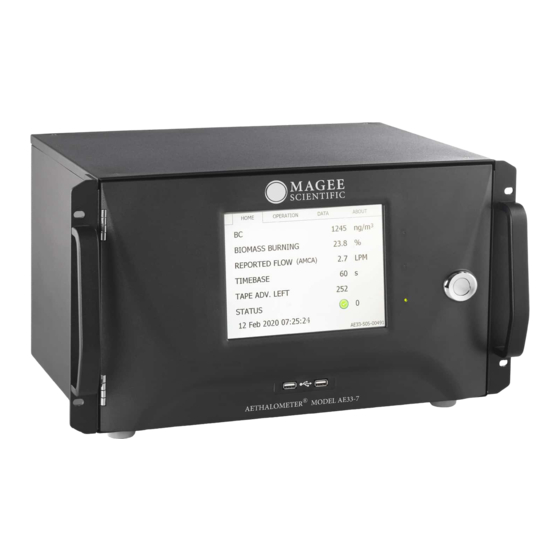
Aethalometer Model AE33 1 GENERAL INFORMATION The Aethalometer® Model AE33. The ‘Next Generation’ Aethalometer®, Model AE33, is a precision instrument which incorporates scientific and technical advances to offer improved measurement performance, user features, communications and interface: and the ability to perform routine performance tests to verify correct operation. -
Page 6: Safety Notes And Labels
Instrument service procedure Service of the instrument must be done only by trained service personnel. Regular service trainings are offered at the Aerosol d.o.o. premises in Europe; and on-line by video for users elsewhere in the world. Please contact support@aerosol.eu arrange a convenient date for training. - Page 7 Aethalometer Model AE33 Electric shock CHECK the A.C. main power supply cord during regular maintenance or other service procedure. If the supply cable is DAMAGED or FRAYED, ALWAYS replace it with a new one. Fire and explosion NEVER install the instrument in explosion-risk areas and never operate the equipment near flammable substances.
- Page 8 Aethalometer Model AE33 Instrument service and repair UNAUTHORISED instrument service and repair procedures will VOID THE WARRANTY. The instrument must only be serviced by authorized personnel. _______________________________________________________________________________________________________ Service manual – Ver. 1.0 October 2020 8/60...
- Page 9 Aethalometer Model AE33 Moving parts During AUTOMATIC tape advance procedure, the measurement chamber is lifted by a motorized lift mechanism. To prevent any injuries to your fingers, NEVER place your hands or fingers into ANY mechanical apertures during the automatic tape advance procedure. During MANUAL chamber lift procedure ALWAYS use the chamber lift locking latch.
-
Page 10: Service Procedures On Main Parts
Aethalometer Model AE33 3 SERVICE PROCEDURES ON MAIN PARTS 3.1 ANALYTICAL CORE ASSEMBLY 3.1.1 ANALYTICAL CORE ASSEMBLY REMOVAL PROCEDURE Tools needed: • Philips (' + ') screwdriver • Push to connect tubing fitting tool (supplied in Aethalometer package); or flat (' – ') screwdriver •... - Page 11 Aethalometer Model AE33 2. Please carefully follow the picture steps in the proceeding: 3. Lift the optical chamber up against its springs, lock it into place with the sliding latch _______________________________________________________________________________________________________ Service manual – Ver. 1.0 October 2020 11/60...
- Page 12 Aethalometer Model AE33 4. Remove cartridge filter (push down on gray fitting rings) 5. Disconnect the optical chamber air sample inlet tube. With one hand hold the light source housing and with the other hand pull up slowly on the flexible inlet tube. 6.
- Page 13 Aethalometer Model AE33 7. Remove filter tape 8. Unscrew the 6 screws which secure the assembly to the chassis: 3 on each side as shown below (green circles) 9. Slightly tilt the assembly while removing it from the chassis. _______________________________________________________________________________________________________ Service manual –...
- Page 14 Aethalometer Model AE33 You can now proceed with further service, maintenance/cleaning or procedures to exchange defective parts on the analytical core assembly. Analytical core re-installation procedure 1. Clean the threads of the 6 mounting screws and apply a drop of Loctite 243 to each one.
-
Page 15: Led Optical Source Replacement
Aethalometer Model AE33 Front panel Older units (units from batch 00 only) have 4 screws on the lower baseplate for attaching the analytical assembly: but do NOT have the two upper stabilizing screws. All subsequent instruments have 2 additional screws at the top of the chamber frame. 3.1.2 LED OPTICAL SOURCE REPLACEMENT Tools needed •... - Page 16 Aethalometer Model AE33 3. Lift the optical chamber up against its springs, lock it into place with the sliding latch 4. Remove cartridge filter (push down on gray fitting rings) 5. Remove lower light guide chamber: press UP on the locking button at the front; turn the chamber to the left until its bayonet fitting releases.
- Page 17 Aethalometer Model AE33 6. Insert the long '+' screwdriver into the two holes on the upper surface of the chamber top piece. Unscrew 2 screws from the holder (top left picture). Hold the lower bayonet housing when detaching the second screw. 7.
-
Page 18: Detector Board Replacement
Aethalometer Model AE33 10. Separate both PCBs (LED source and LED driver) and replace them with new electronics. Check the orientation of the 4 plugs and sockets – there is only ONE correct way! LED source assembling • Put everything back in reverse order (re-attach cover ring, re-connect ribbon cable, re-insert it into upper chamber, re-attach 2 screws with a long ´+´... - Page 19 Aethalometer Model AE33 2. Cleaning equipment • Ethanol • Cotton-tipped swab sticks • Cotton wipe cloths • Can of 'dust removal' pressurized spray with nozzle tube 3. Spare parts • AE33 1 03 903_detector board • AE33 1 99 021_detector board cable •...
- Page 20 Aethalometer Model AE33 4. Remove 5 screws from the detector board and pull it out holding the connector (Note: you may need to pry it gently at each mounting hole, if it is pressed firmly into place.) 5. Detector board replacement •...
-
Page 21: Controller Board Replacement
Aethalometer Model AE33 After any servicing of the analytical core assembly, we highly recommend that a leakage test should be performed once the instrument is operational: see Section 9.4 in the User´s manual. 8. System electrical grounding test Repeat the electrical GND continuity test procedure described in Section 3.1.1. 3.1.4 CONTROLLER BOARD REPLACEMENT 1. -
Page 22: Flow Sensor Replacement
Aethalometer Model AE33 4. Analytical core assembly re-installation procedure Follow the instructions in Section 3.1.1 5. System firmware upgrade after controller board replacement We highly recommend installing the latest firmware version after replacement of the controller board. 6. Recommended leakage test After any servicing of the analytical core assembly, we highly recommend that a leakage test should be performed once the instrument is operational: see Section 9.4 in the User´s manual. - Page 23 Aethalometer Model AE33 • Digital voltmeter (for grounding continuity test) • Can of 'dust removal' pressurized spray with nozzle tube • Screw thread locking adhesive (e.g., 'Loctite 243') • Air flow calibrator, e.g. 'BGI TetraCal' (for leak check testing) 2. Spare parts •...
- Page 24 Aethalometer Model AE33 4. Installation of flow sensors It is important that the arrow on each flow sensor is pointing in the correct direction: left- hand sensor 'down', right-hand sensor 'up'. Bad electrical contacts can cause false readings of the flow sensor. Check that the wiring plug is firmly connected and that pins are properly fitted.
-
Page 25: Tape Sensor Replacement
Aethalometer Model AE33 5. Analytical core assembly re-installation Follow the instructions in Section 3.1.1 6. Recommended leakage test After servicing the analytical core assembly, we highly recommend that a leakage test should be performed once the instrument is operational: see Section 9.4 in the User´s manual. 7. - Page 26 Aethalometer Model AE33 3. Procedure to replace tape sensors • Turn OFF the instrument and unplug the power cord • See Section 3.1.1 and follow the procedure to remove the analytical core • Remove the tape sensor cover, disconnect sensor from the controller board. When re- installing components, do not apply excessive force on fixing screws, since they can break easily.
-
Page 27: Sample Inlet Flow Path Cleaning Procedure
Aethalometer Model AE33 • Anyway, to proceed with this procedure, the chamber must be in the upper position. Open OPERATION/ADVANCED screen and first check the chamber status: If the status is 10, open OPERATION/MANUAL screen and press CHAMBER TAPE. Chamber will move upwards and its status will change to 11. If the status is 20, open OPERATION/MANUAL screen and press CALIBRATE CHAMBER. - Page 28 Aethalometer Model AE33 5. Cleaning equipment • Ethanol • Cotton-tipped swab sticks • Cotton wipe cloths • Can of 'dust removal' pressurized spray with nozzle tube 2. Turn OFF the instrument and unplug the power cord 3. Remove the top cover and lock the optical chamber in the raised position as shown in Section 3.1.1 4.
- Page 29 Aethalometer Model AE33 5. Cleaning procedure of the optical chamber and the flow divider Remove the transparent light guide cylinder and clean it with alcohol Remove the filter tape; cover the suction inlet ports (under the tape) with a wipe cloth and then blow the area clean with compressed gas.
-
Page 30: Interconnection Board
Aethalometer Model AE33 7. System electrical grounding test Repeat the electrical GND continuity test procedure described in Section 3.1.1. 3.2 INTERCONNECTION BOARD Part Number AE33 1 06 903 3.2.1 INTERCONNECTION ELECTRONIC BOARD 1. Tools needed • Philips (‘ + ‘) screwdriver •... - Page 31 Aethalometer Model AE33 Disconnect all connectors from M1-M6 Remove board from snap-top standoffs Wiring AE33 1 99 038_M1 power supply board cable AE33 1 99 035_M2 PC board supply cable AE33 1 99 010_M3 PC board data cable AE33 1 99 039_M4 front panel board cable AE33 1 99 037_M5 controller board cable AE33 1 99 071_M6 back panel board cable _______________________________________________________________________________________________________...
- Page 32 Aethalometer Model AE33 4. CMOS back-up battery • Measured voltage should be 3.3V ± 0.2V • Battery type is VL2330-1HF • Battery is constantly recharged by the instrument supply during power-up operation; and is only discharged during power-down storage. This battery should have a very long service life.
-
Page 33: Fuses
Aethalometer Model AE33 • Note: this test can only be performed while the interconnection board is installed in the instrument, and the power is switched ON. All voltages are low, and this procedure is safe. • Press and hold the push-button switch S1. All 6 LED indicators on the board should light up. - Page 34 Aethalometer Model AE33 1. Tools needed • Philips (' + ') screwdriver • Push to connect tubing fitting tool (supplied in Aethalometer package); or flat (' – ') screwdriver • Tweezers, long-nose pliers • Digital voltmeter (for grounding continuity test) •...
- Page 35 Aethalometer Model AE33 • Remove tubing and disconnect pump cable from the controller board (4-wire plug) • Unscrew 4 hex locking nuts and remove pump. You will need a long extension to reach the 2 nuts towards the center of the instrument. •...
- Page 36 Aethalometer Model AE33 • Re-assemble the pump; re-install it in the instrument; perform all tests. 5. Flow calibration and verification tests After servicing the pump, we highly recommend that calibration and verification of the flow should be done: see Section 9.3 and 9.9 in the User´s manual. 6.
-
Page 37: Rear Panel Data Connector Plate
Aethalometer Model AE33 3.4 REAR PANEL DATA CONNECTOR PLATE Part number AE33 9 08 000 1. Tools needed • Philips (‘ + ‘) screwdriver • Digital voltmeter (for grounding continuity test) 2. Spare parts • PH Cross recessed pan head Screw DIN 7985 M3x6 A2 •... -
Page 38: Power Supply Module
Aethalometer Model AE33 4. System electrical grounding test Repeat the electrical GND continuity test procedure described in Section 3.1.1 3.5 POWER SUPPLY MODULE Part Number AE33 9 06 000 1. Tools needed • Philips (' + ') screwdriver • Tweezers, long-nose pliers •... - Page 39 Aethalometer Model AE33 3. Procedure to disassemble and replace the power supply module • Turn OFF the instrument and unplug power cord • Remove the rear cover (first disconnect the GND wire) • Unscrew 4 screws and slowly take out the power supply module chassis. When it is partly out, disconnect the ribbon cable on the left-hand side.
-
Page 40: Computer
Aethalometer Model AE33 5. Ventilation fan filter Check filter and clean it if necessary 6. System electrical grounding test Repeat the electrical GND continuity test procedure described in Section 3.1.1 * Instruments in production series S02 and earlier have a different Power Supply chassis and board. The only difference is the mounting spacers (M3): consequently, these Power Supply boards have smaller fixing holes. - Page 41 Aethalometer Model AE33 • BN660 M2x4_PH Cross recessed pan head Screw DIN 7985 M2x6 A2 • VGA cable • AE33 1 99 011_ PC power supply cable • AE33 1 99 014_ Ethernet cable • AE33 1 99 016_ Backlight cable •...
- Page 42 • Disconnect PC power and data cable from the interconnection board, remove PC 5. Replacement of Compact Flash memory card • For instruments in earlier production series (S07 or older), please contact Aerosol Customer Support at support@aerosol.eu for a CF card with suitable formatting and pre-loaded files.
-
Page 43: Ball Valve
Aethalometer Model AE33 o Insert card in card reader, right click on new-found drive in your folder browser and format it to NTFS. Follow on-screen instructions as shown below: 6. System electrical grounding test Repeat the electrical GND continuity test procedure described in Section 3.1.1 3.7 BALL VALVE 1. - Page 44 Aethalometer Model AE33 • AE33 1 99 041_Inlet board cable • AE33 0 02 038_ Top holder • AE33 0 03 032_ Valve Fitting C1 • AE33 0 03 033_ Lateral Tee • AE33 0 03 034_ Valve Fitting C2 •...
- Page 45 Aethalometer Model AE33 • Remove chassis mounting screws and take out the ball valve. 4. Re-assembly procedure Reverse the steps described above. Clean all screw threads and put a drop of Loctite on each one before installing. Connect all air flow tubes. Be sure that the sample air inlet tube is pushed firmly all the way onto the top of the optical chamber.
-
Page 46: Front Door Touch-Screen Module
Aethalometer Model AE33 3.8 FRONT DOOR TOUCH-SCREEN MODULE Part number AE33 9 07 000 (front cover is not included) 1. Tools needed • Philips (' + ') screwdriver • Tweezers, long-nose pliers • Digital voltmeter (for grounding continuity test) • Slip-joint pliers 2. - Page 47 Aethalometer Model AE33 4. Touch screen replacement procedure • Remove touch screen cables from the front panel board and touch controller (as indicated in pictures below) • Loosen screws on the left side and remove screws on the right side. Before installing new screen, connect the backlight, data, and power cables.
- Page 48 Aethalometer Model AE33 Remove connector cover, disconnect the front panel data cable and all other cables connected to the front panel board: including the touch screen cable connected to the touch controller. Remove all mounting screws. Minor items such as the touch screen board, USB board and LED drive board may be exchanged if necessary.
-
Page 49: Troubleshooting
Aethalometer Model AE33 4 TROUBLESHOOTING 4.1 STARTUP SCREEN CHECKS Title Description Error Solution Communication Tests communication hardware check cables between computer and problem check electronics analytical core controller (computer, board interconnection board, chamber electronics) Instrument Obtains data (serial hardware check cables data number) from the problem... -
Page 50: Instrument Status
Aethalometer Model AE33 Chamber Optical chamber Chamber locked Release latch, unlock movement test in ‘up’ position chamber hardware error service needed Pump & Flow Test if pump is working pump service needed tube reconnect tubes connections Device Computer operating faulty get new CF card and SW monitoring system test... -
Page 51: Unacceptable Quality Control Test Results
Aethalometer Model AE33 update firmware faulty LED board -> service needed Chamber status Chamber locked Unlock optical chamber 128, 256 Filter tape Not much filter tape Schedule filter tape status remaining replacement Filter tape No filter remaining Replace filter tape status Filter not moving Tighten right spool thumbscrew... -
Page 52: Other Issues
Aethalometer Model AE33 Check for perturbation of room by cycling air-conditioning or heater 4.4 OTHER ISSUES Issue description Possible cause Solution FLOW Reported flow <> set flow Flow not calibrated. calibrate flow Check RAW values at 0 flow for FΣ and F1 under ‘’advance screen’’. - Page 53 Aethalometer Model AE33 Tape advance left status < Low sensitivity of the Replace left tape sensor 250 spots with new filter left tape sensor tape MEASUREMENT DATA Oscillations in BC data Dirty optical chamber Clean optical chamber Air conditioning effects Install Sample Stream Dryer Parameter k exceeds limit Air conditioning effects...
-
Page 54: Software Upgrade
Aethalometer Model AE33 5 SOFTWARE UPGRADE 1. Use only a high quality USB memory drive. Copy the following files to the root directory: - NK.bin or AE33.exe - application software depends on the batch of the AE33, which is described in support user group webpage (SW version number not shown). - ae33coNNN.hex, ae33deNNN.hex, ae33leNNN.hex - three firmware files for version NNN. -
Page 55: Drawings
Aethalometer Model AE33 DRAWINGS Front view Front view, open door _______________________________________________________________________________________________________ Service manual – Ver. 1.0 October 2020 55/60... - Page 56 Aethalometer Model AE33 Rear view Rear view, no cover _______________________________________________________________________________________________________ Service manual – Ver. 1.0 October 2020 56/60...
- Page 57 Aethalometer Model AE33 Exploded view _______________________________________________________________________________________________________ Service manual – Ver. 1.0 October 2020 57/60...
- Page 58 Please contact the service department through our web sites (Service & Support): www.mageescientific.com www.aerosol.eu Please include the serial number of the instrument and a sample of recent data in the communication. Always send the raw files (data, log and setup). Aerosol d.o.o. Kamniška 39A SI-1000 Ljubljana SLOVENIA EUROPE fax: +386 59 191 221 www.aerosol.eu...
- Page 59 Aethalometer Model AE33 8 RETURNS FOR SERVICE Before returning any Magee Scientific instrument for service, please contact either the Magee Scientific or the Aerosol office. Aerosol d.o.o., Kamniška 39A, SI 1000 Ljubljana, Slovenia. tel: +386 1 4391 700 support@aerosol.eu Magee Scientific Corporation, 1916A M.L.
- Page 60 Aethalometer Model AE33 _______________________________________________________________________________________________________ Service manual – Ver. 1.0 October 2020 60/60...
Need help?
Do you have a question about the Magee Scientific Aethalometer AE33 and is the answer not in the manual?
Questions and answers