Advertisement
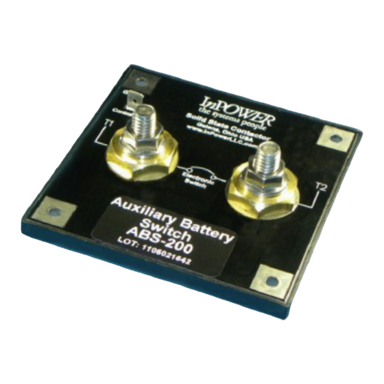
Electronic Auxiliary Battery Switch
Max Current
Stock No.
Type A
Mounting
44410
100
44411
150
44412
175
44413
200
Type A Mounting: Aluminum plate 0.125"x16"x16" or larger
Type B Mounting: wood, plastic or free air
I
ntroduction
InPower's ABS Series Auxiliary Battery Switch is the next generation technology for charging and isolating an auxiliary
battery from a vehicle's chassis battery and alternator. The ABS uses InPower's proven Patent-Pending solid-state
contactor technology incorporating sophisticated microprocessor algorithms that include over-current, over temperature,
and under-voltage sensing.
The basic operating principles are simple. The auxiliary battery is charged from the chassis battery and alternator while
the chassis battery is protected from auxiliary battery load discharge. As the ABS is bidirectional, a charging device such
as a battery charger or genset connected to the auxiliary battery can also supply charging current to the chassis battery.
The ABS switch accomplishes this through the voltage and current monitoring capabilities of its microprocessor
controller. The proper time to transfer power between the chassis battery and the auxiliary battery is based on a
proprietary algorithm that utilizes both battery voltage and current measurements. A "boost start" feature is provided that
will allow the auxiliary battery to supply current to the chassis battery to aid engine starting.
The ABS switch capacity is determined by calculating the maximum alternator output current less the minimum chassis
load current. InPower's ABS Auxiliary Battery Switches are available in 100, 150, 175 and 200 amp models.
UNCONTROLLED DOCUMENT
All information is provided by manufacturer
Updated 9/27/11
www.waytekwire.com
Phone
I
800.328.2724
I
952.949.0765
Fax
I
800.858.0319
I
952.949.0965
Advertisement
Table of Contents

Summary of Contents for WAYTEK InPower ABS-200
- Page 1 Electronic Auxiliary Battery Switch Max Current Stock No. Type A Mounting 44410 44411 44412 44413 Type A Mounting: Aluminum plate 0.125”x16”x16” or larger Type B Mounting: wood, plastic or free air ntroduction InPower’s ABS Series Auxiliary Battery Switch is the next generation technology for charging and isolating an auxiliary battery from a vehicle’s chassis battery and alternator.
- Page 2 Auxiliary Battery Switch Operation Mode A - Charging and isolating an auxiliary battery from the main chassis battery and alternator. The engine is running and the alternator starts supplying current to the chassis battery. When the chassis battery voltage rises above 13.5 volts for 20 seconds, and the auxiliary battery’s voltage is above 7.5 volts, the InPower ABS switch will close, connecting the two batteries.
- Page 3 Auxiliary Battery Switch Do not weld on the vehicle with the Auxiliary Battery Switch installed as damage to the product may result. If electric welding is necessary, disconnect the cables attached to the T1 and T2 terminals. Damage due to electric welding while the unit is installed will void InPower’s warranty.
- Page 4 Auxiliary Battery Switch Installation Procedure, Continued Battery Cable Fusing A fuse must be installed in each cable connecting the ABS switch to the chassis and auxiliary batteries (Refer to Figure 1). Each fuse must be located within 16 inches of the respective battery. Refer to Table A for the minimum fuse size for each ABS switch model. Connect the Power Cables Prepare the two cables to the batteries using a suitable size cable for the current required and install a crimped lug terminal on the end.
- Page 5 Auxiliary Battery Switch www.waytekwire.com UNCONTROLLED DOCUMENT Phone 800.328.2724 952.949.0765 All information is provided by manufacturer 800.858.0319 952.949.0965 Updated 9/27/11...
Need help?
Do you have a question about the InPower ABS-200 and is the answer not in the manual?
Questions and answers