
Summary of Contents for Syntacore SCR1 SDK. Altera Arria-V Starter Kit Edition
- Page 1 SCR1 SDK. Altera Arria-V Starter Kit Edition. Quick Start Guide © Syntacore, info@syntacore.com Version 1.4, 2019-04-08...
-
Page 2: Table Of Contents
Table of Contents Revision History ................ ... - Page 3 10. Appendix B. SDK IRQs .............. ...
- Page 4 Copyright by Syntacore LLC © 2017. ALL RIGHTS RESERVED. STRICTLY CONFIDENTIAL. Information contained in this material is confidential and proprietary to Syntacore LLC and its affiliates and may not be modified, copied, published, disclosed, distributed, displayed or exhibited, in either electronic or printed formats without written authorization of the Syntacore LLC.
-
Page 5: Revision History
Revision History Version Date Description 2017-08-01 Initial revision 2019-01-30 Modifications: • New section: "Windows - USB JTAG Cable drivers installation" • Sections with memory map and IRQ mapping are moved to appendix; • Figure numbering is introduced. 2019-03-21 OpenOCD section updated for RISC-V debug. JTAG speed requirement added. -
Page 6: Setup Equipment
This is a user guide for the Arria V GX based SCR1 SDK Arria V GX FPGA Starter Kit from the Altera. 1. Setup equipment Arria-V based SCR1 SDK HW platform consist of three mandatory components: 1. Arria V GX FPGA Starter Kit https://www.altera.com/products/boards_and_kits/dev-kits/altera/kit-arria-v-starter.html 2. -
Page 7: Sdk Hw Assembly
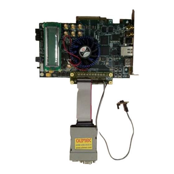
2. SDK HW assembly 2.1. Connecting serial console In order to get access to the board console, it is required to mount HSMC Debug Header Breakout Board (included in Arria-V Starter Devkit) and connect CP2104-MINIEK USB-to-UART converter to the breakout board with external wiring, as described in this section. 2.2. - Page 8 For proper JTAG interface functioning JTAG clock (TckFreq) and system IMPORTANT clock (SysClkFreq) frequencies must satisfy the following relation: SysClkFreq / TckFreq >= 12. You can either connect JTAG port using mounting wires, or apply the existing flat cable from the Olimex kit. For the Olimex kit, some rework IMPORTANT will be needed, it also affects couple of unused pins on the header.
-
Page 9: Arria-V Hw Image Update
Figure 4. Arria V SDK setup 3. Arria-V HW image update 1. Connect board by the ethernet-cable to the network with DHCP-server 2. Power on the board and wait for IP-address to appear at the board LCD-display (IP address may be different): Figure 5. - Page 10 6. Wait for upload completion: Figure 7. Upload completion message 7. Power off the board. Flash update is complete.
-
Page 11: Booting The New Fpga Image
4. Booting the new FPGA image After FGPA image updated successfully, in order to load the new image, you have to do the following sequence after every power on! IMPORTANT Otherwise (by default), system will boot into standard board update portal image. -
Page 12: Resetting The Board
5. Resetting the board: Press PB2 button if you need to reset board to the bootloader. NOTE Corresponding button is in the figure below: Figure 10. RESET (PB2) button 6. UART connection settings • Bps/Par/Bits - 115200 8N1 • speed - 115200 •... -
Page 13: Using Uart Terminal
1. Connect PC to the uart port and open any terminal (minicom is used in the example below) After reset or FPGA firmware update you will see the bootloader prompt: SCR loader v1.0-scr1_RC Copyright (C) 2015-2017 Syntacore. All rights reserved. ISA: RV32IMC [40001104] IMPID: 19040301 BLDID: 19040500... - Page 14 1: xmodem load @addr g: start @addr d: dump mem m: modify mem i: platform info 2. Press button “1” 3. Print required TCM address (in hex) and press “Enter”. “C” character starts to print continuously xload @addr addr: f0000000 CCCCCCCCCCCCCC 1.
-
Page 15: Example: Dhrystone Run From Tcm Memory
+-----------[xmodem upload - Press CTRL-C to quit]------------+ |Sending dhry21-o3lto.bin, 107 blocks: Give your local XMODEM | |receive command now. |Bytes Sent: 13952 BPS:5468 |Transfer complete | READY: press any key to continue... +-------------------------------------------------------------+ 1. After loading completes, status information will be shown: Xmodem successfully received 13952 bytes 7.2. -
Page 16: Using Openocd
Dhrystone Benchmark, Version 2.1 (Language: C) Program compiled without 'register' attribute Compiler flags: -O3 -funroll-loops -fpeel-loops -fgcse-sm -fgcse-las -flto HZ 1000000, CPU MHz 30.000 Execution starts, 500 runs through Dhrystone Time: begin= 48999682, end= 49004684, diff= 5002 Microseconds for one run through Dhrystone: 10.004 Dhrystones per Second: 99960 7.3. -
Page 17: Downloading And Running An Image Using Openocd
$ sudo ${OOCD_ROOT}/bin/openocd -s ${OOCD_ROOT}/share/openocd/scripts -f ${OOCD_ROOT}/share/openocd/scripts/interface/ftdi/olimex-arm-usb-ocd-h.cfg \ -f ${OOCD_ROOT}/share/openocd/scripts/target/syntacore_riscv.cfg or if you build it from sources: $ sudo ${OOCD_ROOT}/src/openocd -s ${OOCD_ROOT}/tcl -f ${OOCD_ROOT}/tcl/interface/ftdi/olimex-arm-usb-ocd-h.cfg \ -f ${OOCD_ROOT}/tcl/target/syntacore_riscv.cfg After execution to the current terminal, you will receive a message about the connection to the RISCV kernel: Open On-Chip Debugger 0.10.0+dev-01972-g01f0c8951 (2019-03-20-20:10) Licensed under GNU GPL v2... - Page 18 halt ; load_image dhry21-o3lto.bin 0xf0000000 bin ; resume 0xf0000200 halt ; load_image dhry21-o3lto.elf 0x0 elf ; resume 0xf0000200 The boot command assumes the location of the file in the current directory. IMPORTANT For a different location, the name of the uploaded file must include a relative path.
-
Page 19: Building Sdk Fpga-Project For The Arria V Gx
8. Building SDK FPGA-project for the Arria V GX SDK 8.1. General structure of the SDK project The composition of the SDK folders is: • doc - SDK and SCR1 user guides • fpga ◦ a5 ▪ scr1 - DE10-Lite FPGA project ▪... -
Page 20: Building Sdk Fpga Project
8.3. Building SDK FPGA project The step-by-step FPGA project build procedure is described below: 8.3.1. FPGA firmware generation (sof-format) • Run Quartus 13.0.1 in GUI-mode • Select and open fpga-project file (a5_sdk.qpf) • Press "Start Compilation" button or sellect from menu Processing → "Start Compilation" Figure 11. - Page 21 Info: ******************************************************************* Info: Running Quartus II 32-bit Convert_programming_file Info: Version 13.0.1 Build 232 06/12/2013 Service Pack 1 SJ Full Version Info: Copyright (C) 1991-2013 Altera Corporation. All rights reserved. Info: Your use of Altera Corporation's design tools, logic functions ...
-
Page 22: Sdk-Specific Pins Assignment In Fpga-Project
Extracting Option bits SREC Extracting FPGA Image SREC Deleting intermediate files • Flash memory image (a5_hw.flash) is generated in the current folder Flash update steps described in section 3 8.3.3. SDK-specific pins assignment in FPGA-project Most of the pins assignments of the SDK project "inherit" from the basic design: Arria V GX Starter Board Reference Manual SDK-specific connection pins are used for interfaces UART0 and OpenOCD/JTAG. -
Page 23: Scr1 Sdk Fpga-Project Functional Description
8.4. SCR1 SDK FPGA-project functional description 8.4.1. Common project structure The SDK project is configured and ready to be built immediately from the repository. The project contains the following main modules: Figure 12. Arria V SDK FPGA project structure Modules description: •... -
Page 24: Description Of The Blocks Used In The Sdk Project
8.4.3. Description of the blocks used in the SDK project 8.4.3.1. SCR1-core Syntacore RISC-V core. The core is supplied as SystemVerilog RTL sources. A detailed description of the external interfaces of the core and other details are described in the document "SCR1 External Architecture Specification". -
Page 25: Build Id
8.4.4.1. BUILD ID PIO-block contains the project build date parameter, which is available for reading by the processor. The parameter FPGA_A5_BUILD_ID is defined in the file scr1_arch_custom.svh. Component base address - 0xFF000000. 8.4.4.2. Onchip RAM Internal bootload memory with bootloader code resides in the FPGA. Memory size - 64KB. -
Page 26: Appendix A. Sdk Memory Map
9. Appendix A. SDK Memory Map Memory map is shown in the table below: Table 2. SCR1 Arria V GX SDK memory map Base address Size Block name Description 0xFFFF0000 64 KB Onchip RAM Internal memory 0xFF010000 32 B UART UART 16550 0x00000000 256 MB... - Page 27 10. Appendix B. SDK IRQs The connection scheme for interrupt lines is given below: Table 3. SCR1 core IRQ connection IRQ line for the SCR1 core IRQ init block UART (UART 16550) 1-31 Not connected (constant level 0)
- Page 28 The latest release (sc-riscv-0.10.0-1972) can be downloaded from the link: https://github.com/syntacore/openocd/releases or you can build it from sources. 11.3.2. Getting the sources $ git clone -b syntacore https://github.com/syntacore/openocd 11.3.3. Building and using OpenOCD Please, refer to the Syntacore OpenOCD wiki page for instructions: https://github.com/syntacore/...
- Page 29 openocd/wiki/OpenOCD-for-sc_riscv32 11.3.4. Windows - USB JTAG Cable drivers installation In order to use Olimex and Digilent JTAG cable with the OpenOCD the correct drivers should be installed at the host PC. After cable is connected to the host PC, the properly installed drivers should appear in the device manager as shown in the figure below: Figure 14.
- Page 30 In many cases, generic WinUSB driver by Microsoft, which can be enforced using Zadig application, can solve the problem: http://zadig.akeo.ie/ Be very very careful! You should see and select the exactly proper USB IMPORTANT device/channel before pressing 'Zadig' WinUSB replace driver button! Don’t press button with no selection or without proper selection! To apply WinUSB driver to Olimex and Digilent devices, just start application, make sure "Options→List all devices"...
Need help?
Do you have a question about the SCR1 SDK. Altera Arria-V Starter Kit Edition and is the answer not in the manual?
Questions and answers