Advertisement
Quick Links
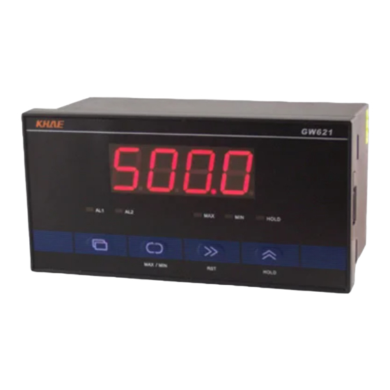
Multifunctional pulse meter instruction manual
1
Characteristics
18 measuring functions to support all kinds of pulse measurement applications
•
It can be equipped with voltage-free contacts, photoelectric switches, proximity switches, rotary
•
encoders and other sensors
High accuracy measurement range 0.0001Hz – 100kHz
•
Memory function of counting value, maximum value and minimum value, memory/no memory
•
can be set
Measure value display update cycle, monitor brightness can be set
•
Two sets of alarm output, alarm type, action error, start delay and close delay can be set
•
Output function of photoelectric isolation transformer, current output (4-20mA) / voltage output
•
(0-10VDC)
Photoelectric isolation communication interface RS-485 / RS-232C, with a baud rate range of
•
2400 ~ 38400bps
2
Model Indication
Dimensions and
Display
160x80x80mm
621
4 LED, 20.3mm
160x80x80mm
631
6 LED, 20.3mm
96x48x82mm
626
4 LED, 20.3mm
96x48x82mm
636
6 LED, 14.2mm
GW621/GW626/GW631/GW636
Pulse counting, rotating pulse measurement and time interval
measurement with high speed plus and minus count
Power
Sensor Power
1 100 - 240VAC
05
2
24V AC/DC
12
24
Alarm Output
1
5VDC
0
None
12VDC
1
Relay
24VDC
2
NPN
Alarm Output
Relay Output
2
0
None
0
None
1
Relay
1
RS-485
2
NPN
2 RS-232C
3
4-20mA
4 0-10VDC
Advertisement

Summary of Contents for KHAE GW6 Series
- Page 1 GW621/GW626/GW631/GW636 Multifunctional pulse meter instruction manual Pulse counting, rotating pulse measurement and time interval measurement with high speed plus and minus count Characteristics 18 measuring functions to support all kinds of pulse measurement applications • It can be equipped with voltage-free contacts, photoelectric switches, proximity switches, rotary •...
- Page 2 Dimensions and opening dimensions of panel Function description of each part of operation panel Description Description Display Holding Light Alarm 1 Indicator Menu Alarm 2 Indicator Switch Max/Min Max Indicator Shift Key / RST Min Indicator 10 Increase Key / HOLD Wiring...
- Page 3 Signal Input Connections The input terminals of IN-1, IN-2, RST and HOLD are internally connected with pull-up resistance, so when the terminals are not wired (suspended), the input on IN is a high level state. When the RST and HOLD terminals are not used and are suspended, the input logic of RST and HOLD should be reversed, that is, the parameter value of RH-N is ON (see "7.
- Page 4 5 indicators AL1 / AL2 / MAX / MIN / HOLD, indicating the working status and display status of the instrument. The panel buttons are used to set the parameters They have a second function, in regular mode. The key is used as the MAX / MIN (maximum / minimum) key to switch between the current values, the maximum value and the minimum value.
- Page 5 Action menu: used to set parameters • that needs to be changed frequently. It consists of 0 ~ 8 parameters selected randomly in the engineer menu. Push enter the action menu. Push to select parameter. Press down in the parameter selection state. Exit to menu.
-
Page 6: Parameters Description
In the state of parameter selection, press to return to the parameter group selection. In the parameter group selection state, press to exit menu and return to the regular pattern. Parameters description Code Name Range Factory Default Description FUNC Function F01 ~ F18 FRQL Input signal range... - Page 7 1. FRQL Input frequency range 2. IN-N, RH-N Input signal logic reversal Parameter Range Pulse with on/off Input signal value 0 ~ 100kHz IN-N=OFF Min. 4.8µs (50kHz) Inside (RH-N=OFF) signal 0 ~ 3kHz Min. 160µs IN-N=ON (RH-N=ON) 0 ~ 30kHz Min.
- Page 8 Code Name Rang Factory Description Default G. AL Alarm parameter set -1999 ~ 9999 (GW621 / GW626) AL - 1 Alarm 1 1000 -199999 ~ 999999 (GW631 / GW636) ALT1 Alarm 1 type HI, LO ALY1 Alarm 1 action error 0 ~ 9999 ALN1 Alarm 1 start delay time 0.0 ~ 599.9s...
- Page 9 Code Name Rang Factory Description Default G. COM Communication parameter set COMM Communication methods OFF, RO, R-W ADDR Local address 1 ~ 255 BAUD Baud rate 2.4k, 4.8k, 9.6k, 19.2k, 38.4k 9.6kbps G. RET Variable feed output parameter set A output: 4 – 20mA DC The output current signal is 0 –...
- Page 10 R-W is set, both the parameters and working status of the instrument can be read and the parameters can be modified. "GW621/GW626/GW631/GW636 Multifunctional Pulse Meter Communication Instructions" contains detailed communication instructions. Download address: http://www.khae.cn/support/manual/pgw620.pdf...
-
Page 11: Functional Description
Functional description The instrument has 18 measuring functions, F01 to F18, and is set in the parameter FUNC. The graphical and literal descriptions of pulse signals in the following paragraphs, if not specified, refer to the case of input uncorrelated closure (IN-N = OFF, RH-N = OFF). F01, F02, F03, F04 F01 - Independent input and subtraction counter F02 - Instruction input plus and minus counter... - Page 12 The counter functions F01, F02, F03 and F04 are measured by using the following formulas: measurement value = count *A_B+C A, B: ratio factor. Set the ratio factor to convert the count value into the unit of measurement. C: the initial value of the counter, so that the measurement starts with the desired value. For example, the encoder with output pulse 1000p/r is used in the measurement of sheet metal length in the following figure.
- Page 13 F05, F06, F07, F08 F05 – Tachometer F06 - Frequency table The pulse signal is input by IN - 2, the number of pulses per The input pulse frequency of IN-2 is measured in HZ. minute is measured, and the speed is displayed in rpm. Setting ratio factors A and B, the measured value can be Setting the ratio factor A and B enables the measured values displayed in the required units.
- Page 14 F11 - Time Difference F12 - Time Slot Show the time between IN - 1 and IN - 2 conduction (T)(s) Display IN - 1 conduction time t(s) Measured value = t × A ÷ B Measured value = t × A ÷ B F13 - Measurement Length F14 –...
- Page 15 F15 - Absolute Ratio F16 - Error Ratio The absolute value between frequencies of IN - 2 F2 and The error between the frequency of IN - 2 F2 and IN - 1 F1 IN - 1 F1 is shown in percentage form. is shown in percentage form.
-
Page 16: Technical Characteristics And Specifications
Technical characteristics and specifications Model GW621 GW626 GW631 GW636 Panel Size 160 x 80mm 96 x 48mm 160 x 80mm 96 x 48mm 4 bits LED, Red 4 bits LED, Red 6 bits LED, Red 6 bits LED, Red Display Height 20.3mm Height 20.3mm Height 20.3mm... - Page 17 Other This instrument does not have power switches and fuses. If necessary, it can be installed in • external lines. Do not install the instrument near devices that can generate strong high frequency waves or • surges (such as high-power converters, motors, welding machines, transformers, etc.). Signal lines should be separately wired away from power lines with high voltage or high current, and not parallel to or within the same cable.
- Page 18 Matters needing attention: Please read the instructions carefully before using the meter. • The instrument should be used in a standard environment (such as temperature, humidity, etc.). • Please do not close the meter, and keep enough space for heat dissipation. Please do not disassemble the meter.
Need help?
Do you have a question about the GW6 Series and is the answer not in the manual?
Questions and answers