
Summary of Contents for MMG TQI-021/1
- Page 1 U S E R M A N U A L T Q I – 0 2 1 / 1 Flow meter signal processing unit August 2010.
-
Page 2: Table Of Contents
TQI-021/1 Contents DESIGNATION, FIELD OF APPLICATION ..................3 SPECIFICATION ..........................3 2.1. Inputs (Figure4.) ........................... 3 2.2. Outputs (Figure 4.) ........................3 2.3. Displays ............................4 2.4. Type selection ..........................4 2.5. Accessories shipped with the equipment ..................4 2.6. -
Page 3: Designation, Field Of Application
(Zener-barrier). The TQI-021/1 calculates the flowrate of the flowing fluid based on the signals of the pulse signals of the flowmeter, and summarizes the volume flowing through during the time of measurement. These values are displayed digitally in technical units. -
Page 4: Displays
More information of other programming data and displays see paragraph 3. 2.4. Type selection The TQI-021/1 signal processing unit is manufactured in two versions according to powering. 3 4 1 7 - 0 - 3 0 0 - A Power 115…230 VAC... -
Page 5: Operating Conditions
The block diagram of TQI-021/1 can be seen on Figure 4.: 3.1. Display unit The construction of the display of TQI-021/1 can be seen on Figure 2. The display functionally consists of three parts: Data display: Displays data set, measured or calculated by the device. The displayed data can consist of max. 8 digits, 10,5 mm high, including decimal point, too. -
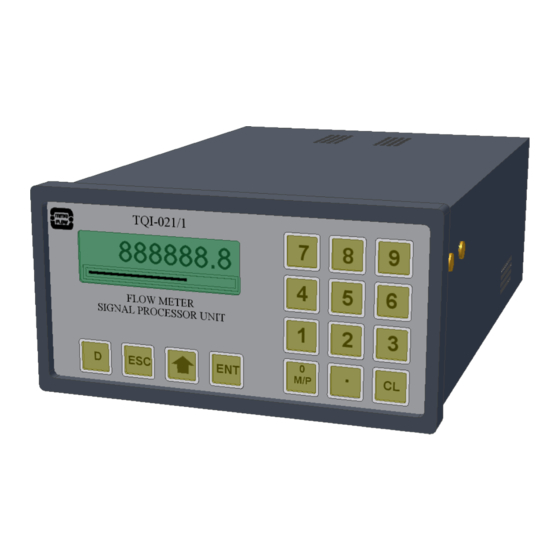
Page 6: Operating The Pushbuttons (Figure 1.)
TQI-021/1 (QL, QH) too, in the place proportional to their values. In case of limit error these marker lines are flashing. 3.2. Operating the pushbuttons (Figure 1.) The four pushbuttons below the display serves for controlling the display, the batching and entering data: ▲... -
Page 7: Batch Control
Identifier (serial number) of the flowmeter connected to the device. Electronic „seal” that is the check number of the measuring system. The program of TQI-021/1 generates this number automatically; there is no other way of setting it. In case any of the data in data group P is changed even temporarily, the check number will change. -
Page 8: Mechanical Construction
Batching suspended by a remote contact can also be terminated by the pushbutton ESC. MECHANICAL CONSTRUCTION TQI-021/1 is encapsulated in a standard size plastic enclosure that is to be built in by Figure 3.The front panel consists of a foil keypad and a graphic LCD display. The rear panel contains the terminals for connecting input and output cables. -
Page 9: Data Stored In The Memory Of The Device
TQI-021/1 DATA STORED IN THE MEMORY OF THE DEVICE No Name Value Unit Description Note 0 Err hl.co..y General error information: Small character means the errorless state. Capital characters signals the error state: H: Q > QH L: Q < QL... - Page 10 TQI-021/1 No Name Value Unit Description Note 35 fIn Input signal selector: 0…pulse signal from the high level inputs (6,7,8) 1…pulse signal from the low level inputs (4,5) 36 fFN Filter-factor in the calculation of the flow rate and the...
- Page 11 TQI-021/1 No Name Value Unit Description Note 75 dT0 0.5 s Minimal time of the frequency measurement 76 dIL 291 pulse Number of high level pulses during the time of dTL 77 dTL 0.609472 s Frequency-measurement time of the low level pulses...
-
Page 12: List Of Figures Figure 1 Keypad, Display
TQI-021/1 MMG FLOW TQI-021/1 V 123456.7 FLOWMETER SIGNAL PROCESSOR Figure 1 Keypad, display Information display Data display 123456.7 Analog display Low signal limit High signal limit [QL] [QH] Flowrate Figure 2. Functions of the display... -
Page 13: Figure 3. Mechanical Dimensions, Panel Cutout
TQI-021/1 ~229 +1.0 -0.0 Figure 3. Mechanical dimensions, panel cutout Batch start contact INP3 Low signal level flowmeter INP1 pulses High signal level flowmeter INP2 150R pulses +24VDC Voltage output for OUT5 powering transmitters. +24VDC Programmable current output OUT4 (0...20mA, max 500ohm) -
Page 14: Figure 5. Rear Panel Arrangements
TQI-021/1 11 12 13 14 15 16 17 2x500mA Mains: 230V 50Hz Power: 10VA IP20 Protection: TQI-021/1 Sn.: RS232/RS485 Line powering 500mA 11 12 13 14 15 16 17 18 19 Voltage: 24VDC Power: Protection: IP20 TQI-021/1 Sn.: RS232/RS485 24V DC powering Figure 5. -
Page 15: Figure 6. Connecting Turbine Meter Sensor
TQI-021/1 In case of non-explosive application Without preamplifier With preamplifier LA6/1 In case of explosive application Without preamplifier With preamplifier LA6/1 Description: 1 Rear panel terminals (TQI 021/1) 4 Shielded cable (6990-1-ABC-3) 2 Turbine sensor (TURBOQUANT) 5 Zener barrier (STAHL9002/22-032-300-111) 3 Turbine sensor, NAMUR preamplifier (LA-6-1) 6 Zener barrier (STAHL9001/01-280-100-101) Figure 6. -
Page 16: Appendix-1: Using The Serial Line Communication
TQI-021/1 APPENDIX-1: USING THE SERIAL LINE COMMUNICATION 1. Settings of the serial line ( determined by item 053:Bd), 600, 1200, 2400, 4800, 9600, 19200 bit/s 8 data bits, No parity bit, 2 stop bits transmitted (but waits only for one). -
Page 17: Structure Of The Command Sent To The Device
TQI-021/1 4. Structure of the command sent to the device Address: Determines to which device the command is sent by the computer. The device interprets the command only if the value of item 051:Adr is equal to this byte. If the value of this byte is = 00H, the device executes the command independently of the value of 051:Adr. - Page 18 TQI-021/1 Info byte = item number STATUS byte: bit(7..4) = 0010B bit(3) = 1, if any of bits of item 000:Err is 1 bit(2) = 1, while batching is in progress bit(1) = 1, while zero calibration is in progress bit(0) = 0 byte is followed by info bytes depending on the received command.
- Page 19 TQI-021/1 - in case of relative type (150) item then bytes 7., 8. points to the number of the item storing the 0 % and 100 % value of the item, in case of other type of floating point data these two bytes do not give information for the user.
Need help?
Do you have a question about the TQI-021/1 and is the answer not in the manual?
Questions and answers