Advertisement
NAVIGATION MAP
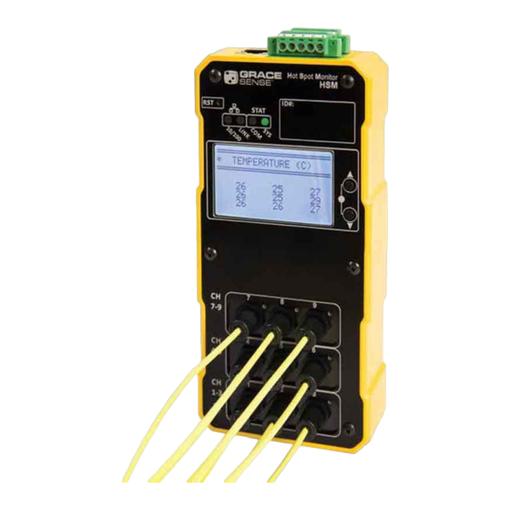
The HSM is equipped with a simple LCD display and a set of buttons which allow for navigation as well as
The HSM �� e�����e� ���h � �����e ��� ������� ��� � �e� �� ������ �h��h ����� ��� ��������� �� �e�� �� ����� ���� �������
basic data display and configuration as shown below.
��� ����������� �� �h��� �e����
FOR MORE INFORMATION VISIT
GRACESENSE.COM
Grace Engineered Products, Inc.
1515 E. Kimberly Road
Davenport, IA 52807
Quick Start Guide
HSM-QSG-EN 1702
OR CALL
1.800.280.9517
QUICK START GUIDE
Installation of the GraceSense™ Hot Spot Monitor (HSM) has been engineered to be simple and
straightforward. This document will describe in detail the 3 steps needed for installation.
Installa�on of the GraceSense Hot Spot Monitoring (HSM) device has been engineered to be simple and straigh�orward.
No specialized knowledge of fiber optics is necessary. A basic understanding of electrical equipment
�he following manual will describe in detail the 3 steps needed for installa�on. �o specialized �nowledge of fiber op�cs is
topology and mounting methods is required.
necessary. A basic understanding of electrical equipment topology and moun�ng methods is re�uired.
Installa�on of the GraceSense Hot Spot Monitoring (HSM) device has been engineered to be simple and straigh�orward.
Installa�on of the GraceSense Hot Spot Monitoring (HSM) device has been engineered to be simple and straigh�orward.
Installa�on of the GraceSense Hot Spot Monitoring (HSM) device has been engineered to be simple and straigh�orward.
Installa�on of the GraceSense Hot Spot Monitoring (HSM) device has been engineered to be simple and straigh�orward.
Installa�on of the GraceSense Hot Spot Monitoring (HSM) device has been engineered to be simple and straigh�orward.
�he following manual will describe in detail the 3 steps needed for installa�on. �o specialized �nowledge of fiber op�cs is
�he following manual will describe in detail the 3 steps needed for installa�on. �o specialized �nowledge of fiber op�cs is
�he following manual will describe in detail the 3 steps needed for installa�on. �o specialized �nowledge of fiber op�cs is
�he following manual will describe in detail the 3 steps needed for installa�on. �o specialized �nowledge of fiber op�cs is
Require� �or �nstalla�on
REQUIRED FOR INSTALLATION
�he following manual will describe in detail the 3 steps needed for installa�on. �o specialized �nowledge of fiber op�cs is
necessary. A basic understanding of electrical equipment topology and moun�ng methods is re�uired.
necessary. A basic understanding of electrical equipment topology and moun�ng methods is re�uired.
necessary. A basic understanding of electrical equipment topology and moun�ng methods is re�uired.
necessary. A basic understanding of electrical equipment topology and moun�ng methods is re�uired.
necessary. A basic understanding of electrical equipment topology and moun�ng methods is re�uired.
Tools for Fiber Mounting:
Components for Hardware
Require� �or �nstalla�on
Require� �or �nstalla�on
Require� �or �nstalla�on
Components �or �ar�ware �nstalla�on:
Tools �or Fiber �oun�ng:
Require� �or �nstalla�on
Installation:
Require� �or �nstalla�on
• Adjustable Wrench
35 mm DI� rail (�"-�") and moun�ng
Adjustable Wrench
• 35 mm DIN rail (6"-8") and
hardware
Components �or �ar�ware �nstalla�on:
• 1.5 mm Allen Key
Tools �or Fiber �oun�ng:
Components �or �ar�ware �nstalla�on:
Tools �or Fiber �oun�ng:
1.5 mm Allen Key
Components �or �ar�ware �nstalla�on:
Tools �or Fiber �oun�ng:
Components �or �ar�ware �nstalla�on:
Tools �or Fiber �oun�ng:
Components �or �ar�ware �nstalla�on:
Tools �or Fiber �oun�ng:
mounting hardware
CA�5 �thernet cable (if connec�ng to �CADA or
�uillo�ne Cu�er
Adjustable Wrench
computer.
35 mm DI� rail (�"-�") and moun�ng
Adjustable Wrench
• Guillotine Cutter
Adjustable Wrench
35 mm DI� rail (�"-�") and moun�ng
Adjustable Wrench
hardware
Adjustable Wrench
• CAT5 Ethernet cable
1.5 mm Allen Key
1.5 mm Allen Key
hardware
1.5 mm Allen Key
1.5 mm Allen Key
1.5 mm Allen Key
CA�5 �thernet cable (if connec�ng to �CADA or
�uillo�ne Cu�er
�uillo�ne Cu�er
(if connecting to SCADA
�- �oun�ng Fi�ture an� �p��al Fiber �nstalla�on
�uillo�ne Cu�er
CA�5 �thernet cable (if connec�ng to �CADA or
�uillo�ne Cu�er
computer.
�uillo�ne Cu�er
computer.
or computer.)
�- �oun�ng Fi�ture an� �p��al Fiber �nstalla�on
�- �oun�ng Fi�ture an� �p��al Fiber �nstalla�on
� - Se�ure the �oun�ng Fi�ture to Busbar an� Conne�t Fiber
�- �oun�ng Fi�ture an� �p��al Fiber �nstalla�on
�- �oun�ng Fi�ture an� �p��al Fiber �nstalla�on
�- �oun�ng Fi�ture an� �p��al Fiber �nstalla�on
1. MOUNTING AND FIBER INSTALLATION
II. Insert the washers and secure it with a nut.
I. Insert the screw with the washer through the
� - Se�ure the �oun�ng Fi�ture to Busbar an� Conne�t Fiber
� - Se�ure the �oun�ng Fi�ture to Busbar an� Conne�t Fiber
A. Secure the mounting fixture to Busbar and Connect Fiber
� - Se�ure the �oun�ng Fi�ture to Busbar an� Conne�t Fiber
� - Se�ure the �oun�ng Fi�ture to Busbar an� Conne�t Fiber
�nsure the hole for fiber inser�on is pointed in
fixture and busbar.
� - Se�ure the �oun�ng Fi�ture to Busbar an� Conne�t Fiber
the direc�on of the fiber rou�ng.
I. Insert the screw with the washer through
II. Insert the washers and secure it with a
I. Insert the screw with the washer through the
II. Insert the washers and secure it with a nut.
I. Insert the screw with the washer through the
II. Insert the washers and secure it with a nut.
I. Insert the screw with the washer through the
II. Insert the washers and secure it with a nut.
I. Insert the screw with the washer through the
II. Insert the washers and secure it with a nut.
the ring-type connector and busbar.
fixture and busbar.
nut. Ensure the hole for fiber insertion is
II. Insert the washers and secure it with a nut.
�nsure the hole for fiber inser�on is pointed in
I. Insert the screw with the washer through the
fixture and busbar.
�nsure the hole for fiber inser�on is pointed in
�nsure the hole for fiber inser�on is pointed in
fixture and busbar.
�nsure the hole for fiber inser�on is pointed in
fixture and busbar.
�nsure the hole for fiber inser�on is pointed in
the direc�on of the fiber rou�ng.
the direc�on of the fiber rou�ng.
fixture and busbar.
pointed in the direction of the fiber routing.
the direc�on of the fiber rou�ng.
the direc�on of the fiber rou�ng.
the direc�on of the fiber rou�ng.
B - Route the Fiber to Low-Voltage Cabinet
B - Route the Fiber to Low-Voltage Cabinet
B - Route the Fiber to Low-Voltage Cabinet
Do not fasten or a�ach A��
B - Route the Fiber to Low-Voltage Cabinet
B - Route the Fiber to Low-Voltage Cabinet
!
!
B - Route the Fiber to Low-Voltage Cabinet
moun�ng hardware (�e-wraps�
R
B. Route the fiber to Low-Voltage Compartment
etc.) to at least a 30 cm (12")
length of fiber between the
!
!
por�on of the probe at high
!
R
!
!
R
DO NOT bend fiber tighter than
!
R
!
DO NOT fasten or attach ANY
v o l t a g e a n d i t s fi r s t n o n -
R
R
energized point of contact.
mounting hardware (tie-wraps,
12mm (1/2") radius
Do ��� bend fiber �ghter
etc.) to at least a 30cm (12")
than 12 mm (1/2") radius
Do ��� bend fiber �ghter
Do ��� bend fiber �ghter
Do ��� bend fiber �ghter
Do ��� bend fiber �ghter
Do ��� bend fiber �ghter
than 12 mm (1/2") radius
than 12 mm (1/2") radius
than 12 mm (1/2") radius
than 12 mm (1/2") radius
than 12 mm (1/2") radius
Keep away from sources of
excessive heat whenever
possible. Fiber probe shall not
be a�ached to surfaces with
Keep away from sources of
Keep away from sources of
Keep away from sources of
Keep away from sources of
te m p e rat u re s exc e e d i n g
Keep away from sources of
excessive heat whenever
excessive heat whenever
excessive heat whenever possible.
Keep away from sources of
100ºC or 200ºF.
excessive heat whenever
excessive heat whenever
possible. Fiber probe shall not
excessive heat whenever
possible. Fiber probe shall not
Fiber probe shall not be attached
possible. Fiber probe shall not
possible. Fiber probe shall not
be a�ached to surfaces with
possible. Fiber probe shall not
be a�ached to surfaces with
be a�ached to surfaces with
be a�ached to surfaces with
to surfaces with temperatures
te m p e rat u re s exc e e d i n g
be a�ached to surfaces with
te m p e rat u re s exc e e d i n g
te m p e rat u re s exc e e d i n g
Fiber
- MAX 100ºC
te m p e rat u re s exc e e d i n g
100ºC or 200ºF.
exceeding 120°C or 248°F
te m p e rat u re s exc e e d i n g
100ºC or 200ºF.
100ºC or 200ºF.
100ºC or 200ºF.
Sensor Tip - MAX 120ºC
100ºC or 200ºF.
unless used along with the high
temperature probe (sold separately).
Fiber
- MAX 100ºC
Fiber
- MAX 100ºC
Fiber
- MAX 100ºC
Fiber
- MAX 100ºC
Fiber
Sensor Tip - MAX 120ºC
- MAX 100ºC
Sensor Tip - MAX 120ºC
Sensor Tip - MAX 120ºC
Sensor Tip - MAX 120ºC
FOR MORE INFORMATION VISIT
GRACESENSE.COM
Sensor Tip - MAX 120ºC
Grace Engineered Products, Inc.
1515 E. Kimberly Road
Davenport, IA 52807
Grace Engineered Products, Inc.
Grace Engineered Products, Inc.
Grace Engineered Products, Inc.
Grace Engineered Products, Inc.
Grace Engineered Products, Inc.
Quick Start Guide
Quick Start Guide
Quick Start Guide
Quick Start Guide
Quick Start Guide
Quick Start Guide
Power Supply Requirements:
Power Supply Requirements:
• Voltage: 12-24 VDC
Voltage: 12-24 VDC (0.12A@24VDC)
(0.12A@24VDC)
Power Supply Requirements:
Power Supply Requirements:
Power Supply Requirements:
Power Supply Requirements:
�ower: 3 Wa�s (Max)
Power Supply Requirements:
35 mm DI� rail (�"-�") and moun�ng
35 mm DI� rail (�"-�") and moun�ng
• Power: 3 Watts (Max)
35 mm DI� rail (�"-�") and moun�ng
hardware
Voltage: 12-24 VDC (0.12A@24VDC)
hardware
Voltage: 12-24 VDC (0.12A@24VDC)
Voltage: 12-24 VDC (0.12A@24VDC)
Voltage: 12-24 VDC (0.12A@24VDC)
hardware
Voltage: 12-24 VDC (0.12A@24VDC)
�ower: 3 Wa�s (Max)
�ower: 3 Wa�s (Max)
CA�5 �thernet cable (if connec�ng to �CADA or
CA�5 �thernet cable (if connec�ng to �CADA or
�ower: 3 Wa�s (Max)
�ower: 3 Wa�s (Max)
CA�5 �thernet cable (if connec�ng to �CADA or
�ower: 3 Wa�s (Max)
computer.
computer.
computer.
III. Insert fiber into the holding fixture and secure it
with a 1.5 mm hex screwdriver.
III. Insert fiber into the holding fixture and
III. Insert fiber into the holding fixture and secure it
III. Insert fiber into the holding fixture and secure it
III. Insert fiber into the holding fixture and secure it
III. Insert fiber into the holding fixture and secure it
with a 1.5 mm hex screwdriver.
secure it with a 1.5mm hex screwdriver.
with a 1.5 mm hex screwdriver.
III. Insert fiber into the holding fixture and secure it
with a 1.5 mm hex screwdriver.
with a 1.5 mm hex screwdriver.
with a 1.5 mm hex screwdriver.
Avo i d r u n n i n g fi b e rs I n t h e
!
direc�on of the fold of the boot to
minimize bending and damage of
the fiber.
Avo i d r u n n i n g fi b e rs I n t h e
Do not fasten or a�ach A��
Avo i d r u n n i n g fi b e rs I n t h e
Do not fasten or a�ach A��
Avo i d r u n n i n g fi b e rs I n t h e
!
!
Do not fasten or a�ach A��
!
Avo i d r u n n i n g fi b e rs I n t h e
Do not fasten or a�ach A��
!
direc�on of the fold of the boot to
moun�ng hardware (�e-wraps�
Avo i d r u n n i n g fi b e rs I n t h e
direc�on of the fold of the boot to
Do not fasten or a�ach A��
moun�ng hardware (�e-wraps�
!
!
!
direc�on of the fold of the boot to
moun�ng hardware (�e-wraps�
direc�on of the fold of the boot to
moun�ng hardware (�e-wraps�
!
Avoid running fibers on sharp
minimize bending and damage of
minimize bending and damage of
etc.) to at least a 30 cm (12")
etc.) to at least a 30 cm (12")
direc�on of the fold of the boot to
moun�ng hardware (�e-wraps�
minimize bending and damage of
etc.) to at least a 30 cm (12")
minimize bending and damage of
etc.) to at least a 30 cm (12")
the fiber.
length of fiber between the
minimize bending and damage of
the fiber.
etc.) to at least a 30 cm (12")
length of fiber between the
edges or in the direction of the
the fiber.
length of fiber between the
the fiber.
length of fiber between the
por�on of the probe at high
por�on of the probe at high
the fiber.
length of fiber between the
fold of the boot to minimize
por�on of the probe at high
por�on of the probe at high
v o l t a g e a n d i t s fi r s t n o n -
por�on of the probe at high
v o l t a g e a n d i t s fi r s t n o n -
v o l t a g e a n d i t s fi r s t n o n -
v o l t a g e a n d i t s fi r s t n o n -
length of fiber
bending and damage to the fiber.
energized point of contact.
energized point of contact.
v o l t a g e a n d i t s fi r s t n o n -
energized point of contact.
energized point of contact.
energized point of contact.
between the
portion of the
probe at high
voltage and
its first non-
energized point
of contact.
OR CALL
1.800.280.9517
Advertisement
Table of Contents

Summary of Contents for GraceSense HSM
- Page 1 Quick Start Guide The HSM �� e�����e� ���h � �����e ��� ������� ��� � �e� �� ������ �h��h ����� ��� ��������� �� �e�� �� ����� ���� ������� straightforward. This document will describe in detail the 3 steps needed for installation.
- Page 2 �unc�on Terminals 6-10 Wiring Interface Terminals 1-5 Terminals 6-10 The first 3 numbers (separated by periods) of the Internet Protocol Version 4 IP address should match that of the HSM being used, while Wiring Interface Number Terminals 1-5 Number Input Voltage...
Need help?
Do you have a question about the HSM and is the answer not in the manual?
Questions and answers