Table of Contents
Advertisement
TLT
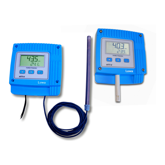
Humidity and Temperature Transmitter HTT-V
Draft created/changed: 31.01.03/TT
Revision: -
Draft released: 18.02.03/DEL
Operating Instruction
Jede unerlaubte Verwendung ist strafbar / Any unpermitted use is subject to prosecution.
Q5.25.45
Page
1 / 18
Document created/changed: 03.08.2012 / Rea
Revision: -
Document released: 03.08.2012 / Rea
Advertisement
Table of Contents

Summary of Contents for Luwa HTT-V Series
- Page 1 Operating Instruction Q5.25.45 Page 1 / 18 Humidity and Temperature Transmitter HTT-V Draft created/changed: 31.01.03/TT Document created/changed: 03.08.2012 / Rea Revision: - Revision: - Draft released: 18.02.03/DEL Document released: 03.08.2012 / Rea Jede unerlaubte Verwendung ist strafbar / Any unpermitted use is subject to prosecution.
-
Page 2: Table Of Contents
Operating Instruction Q5.25.45 Page 2 / 18 Table of contents Draft created/changed: 31.01.03/TT Document created/changed: 03.08.2012 / Rea Revision: - Revision: - Draft released: 18.02.03/DEL Document released: 03.08.2012 / Rea Jede unerlaubte Verwendung ist strafbar / Any unpermitted use is subject to prosecution. -
Page 3: O M P O N E N Ts
Operating Instruction Q5.25.45 Page 3 / 18 AN 28896 Humidity / temperature transmitter type DigiControl HTT-V S room, with 24 VAC/VDC power supply, with LCD display, with standard polyformaldehyde (POM) probe length 90 mm. AN 28897 AN 29164 Humidity / temperature transmitter type DigiControl Humidity / temperature transmitter type DigiControl HTT-V M1, with 24 VAC/VDC power supply, with LCD HTT-V M2, with 24 VAC/VDC power supply, with LCD... -
Page 4: A C C E S S O R I E S A N D S P A R E P A R T S
Operating Instruction Q5.25.45 Page 4 / 18 AN 28928 AN 28929 Sal_SC humidity set 58% 75% Sal_SC humidity 90% AN 29025 AN 28904 Sal_SC humidity 33% Probe assembly bracket for duct 13mm AN 28905 AN 28916 Probe-wall-mounting bracket 13mm (2 pieces) Connector set for HTT-V “S“... - Page 5 Operating Instruction Q5.25.45 Page 5 / 18 AN 28902 AN 29121 Stainless steel probe duct HTT-V M1, length of cable Stainless steel probe duct HTT-V M2, length of cable 10 m To use with high humidity (> 85%) To use with high humidity (> 85%) AN 28901 AN 28907 Probe room HTT-V “S“...
-
Page 6: R O D U C T D E S C R I P T I On
6 / 18 The Luwa HTT-V, S transmitter is a rugged precision measuring instrument for the use in HVAC control and regu- lating systems. It continuously measures up to three times per second, the relative humidity and the actual air temperature and shows the measured value on a large LCD display and simultaneously on two high-precision analogue outputs. -
Page 7: F A C T O R Y S E T I N G S
Operating Instruction Q5.25.45 Page 7 / 18 Type HTT-V room HTT-V duct Item number 28896 28897 24 VDC +/-25% Supply voltage (no galvanic isolation of input and output) min 20mA typical 50 mA max. 80 mA Power consumption (current outputs) -20…+80°... -
Page 8: D I M E N S I O N S
The HTT-V contains ESD-sensitive components. Please refer to the appropriate safety measures. Use only original accessories and spare parts from Luwa Air Engineering AG. Without written permission from Luwa Air Engineering AG it is not allowed to carry out extensions or remodel- ing at the HTT-V. -
Page 9: O U N T I Ng
Operating Instruction Q5.25.45 Page 9 / 18 1. First remove the bottom of the instrument. If necessary, 4 holes can be broken through for the mounting on the wall or at the ventilation duct. The breakthroughs should remain closed when assembling it at a ventilation duct through cable flanges. -
Page 10: O U T S I D E M E A S U R E M E N T
Operating Instruction Q5.25.45 Page 10 / 18 For the outside measurements, use the same cables as for the duct measurements. The probe does not neces- sarily have to be installed inside the duct, but can also be secured by means of a pipe clip to the outside wall of the building. -
Page 11: C O N N E C T I O N S
Operating Instruction Q5.25.45 Page 11 / 18 Probe connection room Output selection 4-20 mA Connection fittings or 0-10V Connector for standard humidi- ty probe Power supply Analogue outputs Probe connection duct Output selection Kabelverschraubung Connection fittings Connector for remote humidity probe 4-20 mA or 0-10V Power supply... - Page 12 Operating Instruction Q5.25.45 Page 12 / 18 Electrical connections This connection must be made by a qualified technician. To make the connection, the transmitter must not be energized. Power suppy connection Output signal selection Voltage (0-10 V) or current (4-20 mA) Before making the connection, you must first check the power supply which is indicated on Select on the miniatur switch the diesred output signal.
-
Page 13: O N F I G U R A T I On
Operating Instruction Q5.25.45 Page 13 / 18 The configuration of the transmitter is done via the keypad which is front mounted under the display. The HTT-V is delivered ready for operation. At the most the analogue outputs and the display options for the application have to be configured. -
Page 14: M E A S U R E M E N T M O D E
Operating Instruction Q5.25.45 Page 14 / 18 Measurement mode To get directly from any menu item to the measurement mode, press for minimum 2 seconds the “Enter” key. The measurement mode is automatically activated 2 minutes after the last key press. The relative air humidity and temperature (°C or °... - Page 15 Operating Instruction Q5.25.45 Page 15 / 18 With this function, the analogue output and the value for manual output can be adjusted from -5%RH to 105%RH. This allows an adaption to inaccurate analogue inputs. 7.7.1 Settings before correction Adjust the desired values for Range L and Range H at the Transmitter HTT-V, for example 0%RH (RLs) and 100%RH (RHs).
-
Page 16: T E M P E R A T U R E U N I T
Operating Instruction Q5.25.45 Page 16 / 18 Temperature Unit *UNIT T In this menu item you can change the unit temperature from ° C (ISO unit) to the US format ° F. The changeover is done by pressing the keys [ ↑ ], [ ↓ ]. Filter settings RH F. - Page 17 A serious error is displayed with an error code. This is important for error analysis. Please send us in such cases always the fault code. Luwa Air Engineering AG has an extensive worldwide network of representatives, which offers a service at any time...
- Page 18 Operating Instruction Q5.25.45 Page 18 / 18 Draft created/changed: 31.01.03/TT Document created/changed: 03.08.2012 / Rea Revision: - Revision: - Draft released: 18.02.03/DEL Document released: 03.08.2012 / Rea Jede unerlaubte Verwendung ist strafbar / Any unpermitted use is subject to prosecution.
Need help?
Do you have a question about the HTT-V Series and is the answer not in the manual?
Questions and answers