Table of Contents
Advertisement
Quick Links
Advertisement
Table of Contents

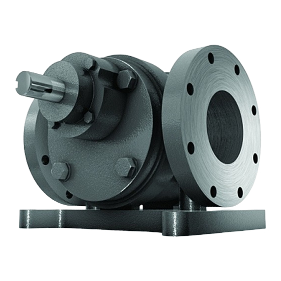
Summary of Contents for Radicon Benzlers Roloid Gear Pump
- Page 1 Roloid Gear Pump Installation & Maintenance IRGP-2.00GB1211...
- Page 2 352'8&76 ,1 7+( 5$1*( Serving an entire spectrum of mechanical drive applications from food, energy, mining and metal; to automotive, aerospace and marine propulsion, we are here to make a positive difference to the supply of drive solutions. Series A Series BD Series BS Series C...
- Page 3 Information IMPORTANT Product Safety Information General - The following information is important in ensuring safety. It must be brought to the attention of personnel involved in the selection of the equipment, those responsible for the design of the machinery in which it is to be incorporated and those involved in its installation, use and maintenance.
-
Page 4: Safety Warning Symbols
Information Section Description Page No Declaration of Conformity / Incorporation General Information External Protection Reading the Nameplate Marking Installation Safety Warning Prior to Installation Lifting Fitting of Components to Pump Input Shaft Mounting to Base Foundation or Machine Flange Mounting to Pipe Work Direction of Rotation Special Instructions for use in a Potentially Explosive Atmosphere Lubrication... -
Page 5: Declaration Of Conformity
Information Declaration of Conformity We hereby declare that Roloid Gear Pumps have been designed in accordance with the following Directives and Standards. ƒ The Machinery Directive 2006/42/EC ƒ EN ISO 12100-1,2 The Safety of Machinery Conforms to all other harmonised standards, tests, and specifications, (In as much as they apply to ƒ... - Page 6 Information 1. General Information The following instructions will help you achieve a satisfactory installation of your Roloid gear pump, Roloid pumps are of simple design using a minimum number of moving parts ensuring that if correctly installed will provide the best possible conditions for a long and trouble free operation. All units are tested and checked prior to despatch, a great deal of care is taken in packing and shipping arrangements to ensure that the unit arrives at the customer in the approved condition.
-
Page 7: Installation
Installation 5. Installation 5.1. Safety Warning WARNING! The customer shall be responsible for the proper use of articles supplied by the company, particularly rotating shafts between the driving members, and the provision of safety guarding. The company shall not be responsible for any injury or damage sustained as a result of the improper use of the articles supplied. - Page 8 Installation 5.5. Mounting to Base Foundation or Machine Flange 5.5.1. Ensure the base foundation or machine flange mounting surface is flat¹, vibration absorbing and torsionally rigid. ( ¹ Maximum permissible flatness error for the mounting surface is 0.12mm) 5.5.2. Align the pump unit with the driving shaft or motor shaft (see Appendix 1). Note: It is important to ensure when aligning unit on a base plate or flange that all machined mounting points are supported over their full area.
-
Page 9: Direction Of Rotation
Installation 5.7. Direction of Rotation 5.7.1. Roloid pumps may be operated in either direction of rotation. If direction of rotation is changed the direction of flow will be reversed, 5.7.2. The direction of rotation and flow relationship are shown below: 5.8. -
Page 10: Motor Connections
Start Up 7. Motor Connections To mains: 7.1. Connection of the electric motor to the mains supply should be made by a qualified person. The current rating of the motor will be identified on the motor plate, and correct sizing of the cables to electrical regulations is essential. -
Page 11: Maintenance
Maintenance Maintenance 10.1. Prior to any maintenance operations 10.1.1. De-energise the drive and secure against un-intentional switch on. 10.1.2. Wait until the unit has cooled down – Danger of skin burns & pressure build up. 10.2. Replacing Oil Seals Periodically worn oil seals may require replacement These instructions apply only to pump units fitted with rubber lip type seals, (for units fitted with mechanical seals consult the seal manufacturer’s instructions) 10.2.1. -
Page 12: Problem Solving
Problem Solving 11. Fault diagnosis 11.1. Pump Unit Problems: Symptom Possible Causes Remedy Fill the pump and its suction pipe completely with the Lack of Prime liquid being handled, Bleed the pump and piping to remove air. Pump Drive is Interrupted or Speed is Too Low Check drive coupling and motor connection Check discharge line for blockages. -
Page 13: Shaft Alignment
Appendix 1 Shaft Alignment Errors of alignment fall into categories of Angularity (fig1) and Eccentricity (fig 2) or a combination of both, errors of angularity should be checked and corrected before the errors of eccentricity Errors of Angularity Errors of angularity can be checked using the following method: Place a mark on both driving and driven hubs and measure the gap between them adjacent to the marks using a block gauge and feelers at position 1 (see fig 3) then rotate both shafts together a quarter turn keeping the marks aligned and take a another measurement at position 2, further measurements should be taken at positions 3 and 4... -
Page 14: Parts List
Appendix 2 Parts List Body Pipe Flange (x2) 19 Pipe Flange Fastenings End Cover (Oil Seal) Oil Seal (x2) Foot Fastenings End Cover (Non Driving) Sealing O'Rings (x2) 21 Pipe Flange Fastenings End Cover (Driving) Bearings (set of 4) Foot Fastenings Foot Ring Dowels (x2) Cover Fastenings... - Page 15 CONTACT US AUSTRALIA DENMARK SWEDEN & NORWAY UNITED KINGDOM Radicon Transmission Benzler Transmission A/S AB Benzlers Radicon Transmission UK Ltd (Australia) PTY Ltd Dalager 1 Porfyrgatan Unit J3 DK-2605 Brøndby, 254 68 Helsingborg Lowfields Business Park, Australia Denmark Sweden Lowfields Way, Elland...
- Page 16 Denmark +45 36 340300 Finland +358 9 3401716 Germany +49 800 3504000 Italy +39 02 824 3511 Sweden +46 42 186800 The Netherlands +31 77 3245900 www.benzlers.com Radicon Thailand +66 38459044 United Kingdom +44 1484 465800 USA +1 847 5939910 www.radicon.com...
Need help?
Do you have a question about the Benzlers Roloid Gear Pump and is the answer not in the manual?
Questions and answers