Advertisement
Quick Links
MX PRO BRAKE MINIMUM SETTINGS
The MX has 6 brake minimum settings. Setting 1 is the minimum brakes and settings 2, 3, 4, 5 & 6
increase the minimum braking "strength". Setting 1 gives the most progressive braking whilst 6
gives the most aggressive. Note: the maximum braking available is engaged when the throttle
control is in the full brake position. The "strength" of the brakes is dependent on the motor type
and motor wind being used, generally 'hot' motors will give the strongest brakes.
To check the current brake minimum setting turn on the MX, then press and hold the set button for
4 seconds, then release. The LED will flash dimly showing the currently set brake minimum setting,
see the table below. To change the brake setting press and release the set button whilst the MX is
displaying the currently set brake minimum value. Once set turn off the MX to store the setting.
1
"Dim Flash"
2
etc
3
4
5
6
MX LAUNCH CONTROL
The MX has "launch control" available which is very useful to give an "assisted" start line response.
From the race start launch control will provide maximum power and acceleration until full throttle
is reached. After full throttle has been reached and held for 1 second, the throttle response will go
back to the profile that has been set. Note: use launch control wisely and take care as it's very fast!
To set launch control, hold the transmitter throttle control in the full brake position for 4 seconds,
launch control will then be active. Note: the MX will also make a 'beep' to help with bench testing.
MX INTERNAL POWER PROTECTION
The MX has in-built protection to help avoid damage. If the MX detects over-temperature due to a
fault, extreme overload running or using without a schottky diode it will run but only very slowly.
You MUST stop and check it immediately. If the MX gets hot caused by a fault or being subjected
to extreme operating conditions etc the user may experience the in-built protection continuously.
If any prolonged abnormal operation is experienced the MX should NOT be used as damage may
result. Stop using the MX until either the fault is found or it has been returned to MRT for testing.
For support telephone or fax MRT on +44(0)870 1624955 or Email support@team-mrt.com
MX PRO OPTIONS & USER NOTES
The MX set-up button may be 'unplugged' if required, this is useful when soldering to connections
or when the button is to be situated in an external position. An optional extension set-up button
lead is available as MRT option part no. 9007 (also a replacement set-up button MRT part no. 9006)
The MX may be re-reprogrammed via data port (by MRT) if firmware profile upgrades are required.
The MX has a built-in heatsink under its MX label. Upgrades for future include optional MX heatsink
and MX high-flo micro fan unit for direct fitting, these options will help in extreme heat conditions.
It is recommended that MX Pro power plugs (if fitted) and leads/connectors are replaced following
long periods of use, as unreliable/worn connections could result in impaired operation or damage.
MX PRO TECHNICAL SPECIFICATIONS
Case Dimensions . . . . . . . . . . 24x24x14mm
Weight (no wires) . . . . . . . . . Approx. 20g
Voltage Input (4-7 cells) . . . . 4.8V to 8.4V
Drive On-Resistance. . . . . . . . 0.000216 Ohms
PWM Frequency Range. . . . . . 1KHz - 3.3KHz
†
Drive Current . . . . . . . . . . . . 1080A
Power Profiles . . . . . . . . . . . . 6 selectable
'Dual-Active' VDF Logic . . . . . Yes
Launch Control . . . . . . . . . . . Yes
†
Combined MOSFET Transistor Rating at 25
€C Junction Temperature
"Dim Flash"
Brake minimum 0% of maximum
Brake minimum 16% of maximum
Brake minimum 32% of maximum
Brake minimum 48% of maximum
Brake minimum 64% of maximum
Brake minimum 80% of maximum
Brake On-Resistance . . . . . . . . . 0.000433 Ohms
†
Brake Current. . . . . . . . . . . . . . 540A
Regenerative Braking. . . . . . . . . Yes
Brake Minimum Settings . . . . . . 6 selectable
Rx Supply Output . . . . . . . . . . . . 6V/3A (peak)
Rx Supply Priority/Protection . . Yes
Full Water and Dust Protection . Yes 100%
Thermal Protection. . . . . . . . . . . Yes inc brakes
Re-programmable Firmware. . . . Yes (data port)
258 DOVER ROAD, FOLKESTONE, KENT, CT19 6NS, ENGLAND.
TELEPHONE/FAX (UK) 0870 1624955 www.team-mrt.com
ver 1.02
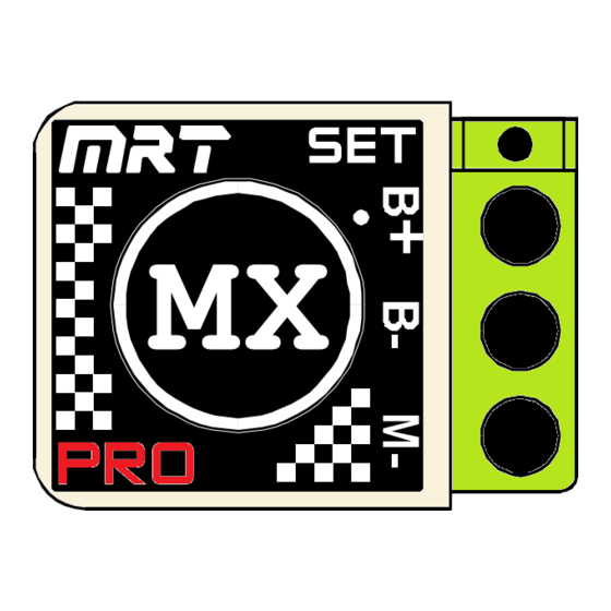
M X
SET
MX
PRO
Advertisement

Summary of Contents for MODEL RACING TECHNOLOGY MX PRO
- Page 1 MX high-flo micro fan unit for direct fitting, these options will help in extreme heat conditions. It is recommended that MX Pro power plugs (if fitted) and leads/connectors are replaced following long periods of use, as unreliable/worn connections could result in impaired operation or damage.
- Page 2 (from centre). A basic type transmitter should have the throttle trim centred. Once the transmitter Note:If receiver battery has been set to your MX Pro the channel 2 servo reversing switch (if fitted) should not be moved. is used leave MX on/off switch set to 'off’.
Need help?
Do you have a question about the MX PRO and is the answer not in the manual?
Questions and answers