
Summary of Contents for MP3 Solid Air WK25 Series
- Page 1 Solid Air Brandkleppen manual ® WH25 Brandkleppen manual WH45 WK25 WK45 Postbus 22756 1100 DG Amsterdam Z.O. Tel.: +31 (0)20 696 69 95 Fax: +31 (0) 20 691 30 62 mail@solid-air.nl www.solid-air.nl...
- Page 2 Via G. La Pira, 9 A-B Camposampiero 3 5 0 1 2 P D - I t a l y www.mp3-italia.it MAINTENANCE AND USE MANUAL WK25 Rectangular fire damper with low pressure drop 500 Pa Brandkleppen manual WH25 WH45 WK25...
-
Page 3: Product Presentation
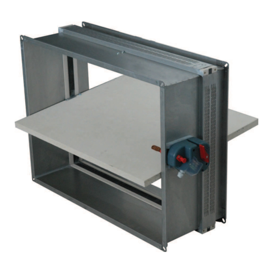
Solid Air ® 1. PRODUCT PRESENTATION The WK25 rectangular fire dampers are installed in ventilation ducts inside walls to stop a fire from spreading. They have a modular mechanism, entirely outside the walls. The duct is built in galvanised steel. The fire damper can be fitted with a simple thermal fuse, or a remote controlled automatic mechanism. - Page 4 Solid Air ® FIRE RESISTANCE IN COMPLIANCE WITH EN 13501-3: 2005 (500 Pa) MECHANICAL FIRE INSTALLATION MATERIAL DIMENSIONS CLASSIFICATION ORIENTATION DIRECTION Aerated concrete Horizontal or vertical 100X200 to EI 120 S Indifferent Thickness 100 mm blade axis 800X600 Density 550 kg/m WALL Plasterboard type Horizontal or vertical...
-
Page 5: Handling And Storage
Solid Air ® Certificates: 5. HANDLING AND STORAGE Since this is safety equipment, the fire damper needs to be stored, handled and installed with care. Attention: • Avoid contact with water and exposure to excessive dampness. • Avoid damage to sealing/gasket during installation. Be careful especially to the external sealing/gasket. •... - Page 6 Solid Air ® HOLES AND SEALING: Attention: Make sure the damper and duct are correctly aligned. The WK25 damper does not have a specific air passage direction. Base and height dimensions indicated below refer to the nominal fire damper dimensions. On 100 mm concrete floor On 150 mm concrete floor: Floor hole dimension: B + 70mm, H + 70mm...
- Page 7 Solid Air ® On plasterboard 98/48 Wall hole dimension: B + 75mm, H + 75mm Layers of standard BA 13 plasterboard panels. • rock wool (80 kg/m³). • Damper installation: A rectangular hole sized (B + 75 mm) x (H + 75 mm) must be provided in the wall with a frame made by metal profiles ideal for use with plasterboard (min.
- Page 8 Solid Air ® Paired installation: The patented WK25 rectangular fire dampers can be paired side-by-side or vertically using the custom connection kit which includes a thermal expanding gasket to be placed between the two dampers. The pair of dampers, may be installed in any type of vertical wall in the same way as a single damper.
- Page 9 Solid Air ® Switching off (blade closing): Manual: Push the off button. Automatic: When the temperature in the duct exceeds 70°, the thermal fuse melts and the blade closes. Resetting: Manual resetting: Turn the lever anti-clockwise. Options: • S2 : End and start position contacts (micro switches). On the S1-25 electronic card, connect the NC / NO / C for the start contact (DCU) and the NC / NO / C for the end contact (FCU).
- Page 10 Solid Air ® 8. DIMENSIONS : BLADE EXPOSURE ! " Brandkleppen manual WH25 WH45 WK25 WK45 1MLWK25R0G Solid Air Luchtverdeeltechniek BV Telefoon (020) 696 69 95 Fax (020) 691 30 62 www.solid-air.nl Brandkleppen manual 06 2013 ®...
- Page 11 Solid Air ® 9. ELECTRICAL CONNECTIONS ELECTRICAL CONNECTIONS WARNING: Electrical connection of the damper to the WARNING: Electrical connection of the damper to the mains must only be done by a qualified electrician. mains must only be done by a qualified electrician. WK25 B Option S2 connection: Electronic card S1-25...
-
Page 12: Electrical Specifications
Solid Air ® WK25 MOTORISED VERSION (V/D): To perform electrical connections proceed as follows: Make sure the mains voltage and frequency correspond to those for which the device is set up (see the nameplate); Make the connection in compliance with the wiring diagram shown below. MOTOR WIRING 10. - Page 13 12. EC declaration of conformity 1MLWK25R0G...
Need help?
Do you have a question about the Solid Air WK25 Series and is the answer not in the manual?
Questions and answers