Table of Contents

Related Manuals for Micom Autodoor EDM-MD Series

Summary of Contents for Micom Autodoor EDM-MD Series
- Page 1 EDM-MD Series Installation Manual MICOM AUTODOOR Automatic Sliding Door Operator Model: EDM MD Original Instructions EN16005 Compliant INSTALLATION MANUAL OSAKA – JAPAN www.micomautodoor.com REVISED DATE: JUNE 2014 No. MD0001 Ver1 Page 1...
- Page 2 EDM-MD Series Installation Manual WARNING: Avoidance of Injury, Electric shock and Fire Safety Beams MUST be installed to ensure threshold safety. Installation and adjustment must be performed by approved personnel only. Repair and/or alteration to the control box and motor are prohibited.
-
Page 3: Table Of Contents
EDM-MD Series Installation Manual Contents Section Product Description 1.1 Introduction 1.2 EN16005 Compliance 1.3 Delivery EDM MD Series 2.1 Complete Operator Parts 2.2 EDM MD SMB (EN16005) Installation 3.1 Base Rail 3.2 Side View Drawing 3.3 EDM-MD Front View 3.4 Mounting Doors 3.5 Smooth Operation... -
Page 4: Product Description
1. Product Description 1.1 Introduction EDM-MD Series is designed to provide a high quality yet economical automatic sliding door solution for easy open and close operation whilst offering variable function adjustment of single or double door leaves up to 100kg per leaf. -
Page 5: En16005 Compliance
BEA IXIO-S & Optex 0A-Axis-T 1.3 Delivery MICOM EDM-MD Series can be supplied in several formats as follows: Complete Operator consisting of: Base Rail, Cover, Control Box, Connection Harness, Motor Gear Box, Connection Terminal, End Covers, Tooth Belt, Belt Bracket Link Assembly, Belt Connection Single & Double Door, Belt Tightening / Idle Pulley Assembly, Hanger Roller Brackets x4 and Stopper x 2. - Page 6 EDM-MD Series Installation Manual Accessories Sensor / Threshold Safety - Microwave or Infrared detection sensors and safety beam products available. Function Selector Switch – 4 Position Rotary switch available (Closed, Exit, Auto, Open & Emergency Exit Option) Door Profile Solutions – Various Fixed and Moving profile designs available without glass.
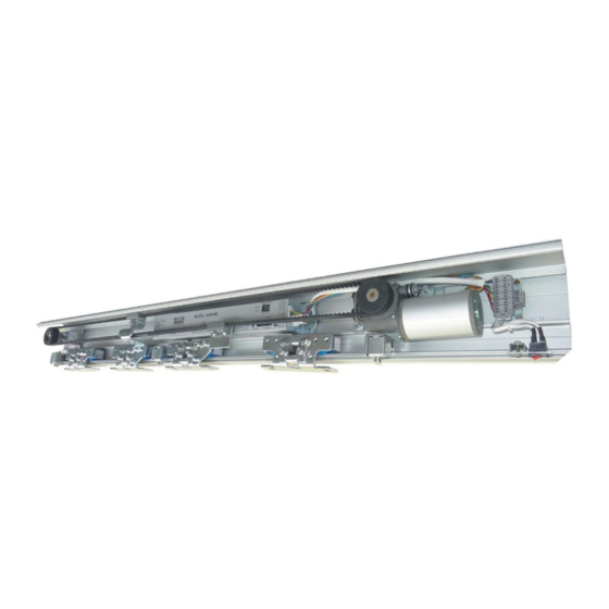
- Page 7 EDM-MD Series Installation Manual 2. MICOM EDM MD Series 2.1 EDM MD Complete Operator Parts Description Belt Tightening / Idle Pulley Bracket Assembly Hanger Roller Bracket with Belt Bracket Link Assembly (Double Leaf) Tooth Belt Hanger Roller Bracket with Belt Bracket Link Assembly (Single Leaf)
- Page 8 EDM-MD Series Installation Manual 2.2 EDM MD – SENSOR & BATTERY MONITORING BOARD (SMB) - EN16005 COMPLIANCE (European Regulation – Option outside of EU) 2.2.1 SMB Description SMB output to Control Box Internal Sensor Input External Sensor Input LED Error Indicator...
- Page 9 EDM-MD Series Installation Manual 2.2.2 SMB - Function Selector Switch - 4 Position Key Note: If SMB is not used, please refer to section 10.1 for MICOM Function Selector - 4 Position Symbol Description Closed / Locked Exit Only Automatic Hold Open Exit –...
-
Page 10: Installation
EDM-MD Series Installation Manual 3. Installation 3.1 Base Rail Installation CAUTION: Reduce risk of injury. Ensure installation area is clear of tripping hazards. Ensure work area is clear of pedestrians and there is a restricted pedestrian access at all times during works being carried out. -
Page 11: Edm-Md Front View
EDM-MD Series Installation Manual 3.3 EDM-MD Front View Page 11... -
Page 12: Mounting Doors
EDM-MD Series Installation Manual 3.4 Mounting Doors Position hanger roller brackets on top of door leaf. Ensure hanger brackets are aligned, then secure in place. Loosen hanger bracket retainer to mount doors on rail. Mount doors on rail. Adjust and secure hanger bracket retainer 2mm from underside of base rail. -
Page 13: Set Up & Operation
EDM-MD Series Installation Manual Note: Teaching data will be stored within the control unit, even if the main power is off. Once the mains power is turned on, the stored data will be reloaded and door will continue its operation with need to re-learn it’s stoke. -
Page 14: Control Box
EDM-MD Series Installation Manual 5.2 Control Box Assembly EDM MD Power Input Plug in 200~240VAC 2. RUN/PRG switch Slide switch to change from RUN mode to PROGRAM mode 3. TEST / UP & SET Buttons TEST Button – Used to check the basic function of the operator when servicing or installation. - Page 15 EDM-MD Series Installation Manual E1 : Open error (Obstruction during the opening cycle) E2 : Closer error (Obstruction during the closing cycle) E4 : Loose belt (Longer stroke than stored data) E6 : E-lock error (no un-lock signal input) ‘PROGRAM’ Mode When in PROGRAM mode, changes to operational parameter values can be made.
-
Page 16: Basic Setting Code
EDM-MD Series Installation Manual 6. Setting 6.1 Basic Setting Code (Set the slide switch to PROGRAM) Factory Code Volume setting Function Remarks LED1 LED2 Hold Open Time 1-9sec, A:10sec, B:20sec, C:30sec, D:40sec, E:50sec F:60sec. 1~F Open High 0~A Setting of open high speed... -
Page 17: Partial Open
EDM-MD Series Installation Manual 6.2 Hold Open Time Value Open Time (sec.) 6.3 Partial Open (Energy Saving) % Value Partial Open 6.4 Open Delay (E-Lock) Value Time Delay (After Activation) 0.1 sec 0.5 sec 1.0 sec 7. Obstruction Detection CAUTION: To avoid risk of injury to pedestrians, it is always recommended to install threshold safety devices such as safety beams or types threshold protection. -
Page 18: Specification
EDM-MD Series Installation Manual 8. EDM MD Basic Wiring 9. Specification Model MD-S MD-D Application Single Double Door Weight (max) 100kg 100kg x2 Power Consumption 200 -240V AC, 0.7A Power Output 24V DC, 300mA Manual door opening/closing 24.5 ~ 39.2N (2.5 ~ 4kgf) 29.4 ~ 49.0N (3~5kgf) -
Page 19: Optional Accessories
EDM-MD Series Installation Manual 10. Optional Accessories 10.1 MICOM Function Selector Switches - 4 Positions with Rotary Knob MICOM Function Selector Switches offer several options of door control. As either a rotary knob or with a secure key, allows selection of 4 to 5 separate door modes. Economic in design, MICOM Function Selectors are easy to install and operate. -
Page 20: Wiring Drawing
EDM-MD Series Installation Manual 10.2 Wiring Drawing - MICOM Function Selector Switch – Available in 2 configurations 4 Position with Rotary Knob 10.2.1 Rotary Function Selector - 4 Position Page 20... - Page 21 EDM-MD Series Installation Manual 10.2.2 Rotary Function Selector Switch - 4 Positions with Push Button - Exit Page 21...
- Page 22 EDM-MD Series Installation Manual 11. Basic Setting Table – Cut out MICOM EDM MD LED1 Function LED2 - Adjustment Factory Setting Hold Open Time 1 ~ F Steps Open High Speed (500mm/s MAX) 0 ~ A Steps Open Low Speed...
- Page 23 E-Mail: info@micomautodoor.com Copyright © 2011 MICOM Autodoor The contents of the document are the sole property of MICOM Autodoor. The direct or indirect sales, copying, scanning, publication, modification or adaptation of any part of this document is prohibited without written consent of MICOM Autodoor.
Need help?
Do you have a question about the EDM-MD Series and is the answer not in the manual?
Questions and answers