Table of Contents
Advertisement
Quick Links
Advertisement
Table of Contents

Summary of Contents for FERN360 FGES-VB T Series
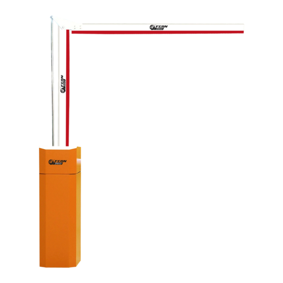
- Page 1 User Manual FERN360 Barrier Arm FGES-VBxxx-T Automa�c Lane Barriers...
-
Page 2: Table Of Contents
FERN360 Barrier Arm FGES-VBxxx-T User Manual Contents 1. T Series Automatic Barrier Structure, Functions & Specifications ..............2 Structure ............................2 Functions............................3 T echnical Data ........................... 4 Installation Guide .............................. 5 2.1 Requirements ............................5 2.2 Barrier Installation ........................... 7 2.2.1... -
Page 3: T Seriesautomatic Barrier Structure, Functions& Specifications
FERN360 Barrier Arm FGES-VBxxx-T User Manual Thank you for selec�ng our T-Series Automa�c Lane Barrier (ALB). Using our cut�ng-edge control systems, we bring to you a flagship model specifically designed for manual toll lane and carparks. This manual provides the technical specifica�on and detailed maintenance procedure for the ALB. -
Page 4: Functions
FERN360 Barrier Arm FGES-VBxxx-T User Manual � Housing Unit:Spray painted with a beau�ful finish, the color can be changed to customer preference. The housing is treated for anti-corrosion. � Barrier Arm:This model can be fi�ed with different barrier arms such as the KB4 (cylinder aluminum arm), KB5 (Octagonal Aluminum arm), ZKB5 (Octagonal Folding arm) and KB7 (An�-Smashing arm). -
Page 5: Technicaldata
FERN360 Barrier Arm FGES-VBxxx-T User Manual TechnicalData Model/ Technical Data KB4/4M KB4/4.5M KB4/5.5M KB4/5.5M KB4/6.0M KB4/6.0M Maximum Arm Length KB5/4M KB5/4.5M KB5/5.5M KB5/5.5M KB5/6.0M KB5/6.0M Rising and < 0.9S < 1.4S < 2.0S < 2.5S < 3.0S < 3.5S Lowering Time <... -
Page 6: Installation Guide
FERN360 Barrier Arm FGES-VBxxx-T User Manual Installation Guide 2.1 Requirements Founda�on Selec�on and Construc�on Coil Reference Fig. 2 Coil Placement Reference � Coil Requirement:Recommended to use 2m×2m coil. Its central axis should be directly beneath the Barrier Arm(fig.2). � Selec�ng a suitable founda�on:Foundation is required to be built 300mm away from the curb,there must be clearance for the arm to swing 90°... - Page 7 FERN360 Barrier Arm FGES-VBxxx-T User Manual � Founda�on diameters:400mm(depth)×500mm(length)×500mm(width) � Foot and Expansion Bolt: (Fig.5) � To be installed 50mm from founda�on; 100mm of bolt thread is required to be exposed. Fig. 5 Fig.6 � Foot and expansion bolt are provided with the machine if they are not readily available or no embedded bolts are present on site.
-
Page 8: Barrier Installation
FERN360 Barrier Arm FGES-VBxxx-T User Manual � Note:Drilling diameter Φ16mm. Drilling can only be done after cement has settled in. � Cable conduit: Foundation should be embedded with 3 units of 1 inch PVC piping. One pipe specifically for the coil wire, to be guided to the roadside, 50mm below ground. -
Page 9: Arm Installation
FERN360 Barrier Arm FGES-VBxxx-T User Manual CAUTIONS: * Duringinstallation, electricity mustbe isolated from the machine. * Handle machine with care. Prevent scratchingthe body and damaging the paint. * Where aesthetics are concerned, it is best to level the arm with the ground, placingit parallel to the oncomingvehiclesand lane. -
Page 10: Kb5Arm Installation Guide
FERN360 Barrier Arm FGES-VBxxx-T User Manual Remove arm from packaging. � Insert the arm diagonally into the flange, aligning to the holes. � The logo and warning sign should face the oncoming vehicles. � Insert an M14×110 hexagon bolt through the holes and �ghten the bolt �... -
Page 11: Zkb13Arminstallation Guide
FERN360 Barrier Arm FGES-VBxxx-T User Manual 2.3.4 ZKB13ArmInstallation Guide Fig.10 ZKB13 Installation 2.3.5 KB13Arm Installation Guide Fig.11 KB13 Installation 10 | P a g e... -
Page 12: Barrier Cover
FERN360 Barrier Arm FGES-VBxxx-T User Manual 2.3.6 Barrier Cover Raise the arm to the ver�cal position � Use the key supplied to unlock the cover. � Push forward and lift up the cover to en�rely remove it. � ElectricalInstallation TVD9L Automatic Barrier Inverter, frequency controller (Fig.12), is the heart and soul of our integrated T-series barrier. - Page 13 FERN360 Barrier Arm FGES-VBxxx-T User Manual DIP switch controls 1-6: � Numbers 1 , 2 :Arm control mode: ARM CONTROL Double signal controls arm. Double signal controls arm, Car leaves coil lowers arm. Lowering signal controls arm, lowering signal not detected raises arm.
-
Page 14: Arm Direction
FERN360 Barrier Arm FGES-VBxxx-T User Manual arm. � External Vehicle Signal (also suitable for using external V.L.D) :Similarly using the 24V+ terminal, it can be used to trigger VD terminal to simulate the automated lowering system and anti-smash control. OUTPUT: �... - Page 15 FERN360 Barrier Arm FGES-VBxxx-T User Manual Remove two of the INNER M10 HEX screws. Remove the swing and its balancing spring. Reinstall to the desired direction. Remove two of the INNER M10 HEX screws. Remove the ARM and its spring. Reinstall to the desired direc�on by replacing the swing and M10 HEX screws, but do...
- Page 16 FERN360 Barrier Arm FGES-VBxxx-T User Manual swing, turning the arm plate to a horizontal position and �ghten the M14*50 Hex screw; The crank and linkage is in a stretched state, adjust it by moving the swing and turning the arm plate into the ver�cal position.
-
Page 17: Safety Precautions
FERN360 Barrier Arm FGES-VBxxx-T User Manual Reinstall Barrier cover and lock the housing unit door to complete the process. Safety Precautions Because the system uses high voltage up to 220-240V, non-qualified personnel are � advised to refrain from maintaining or working on the equipment. -
Page 18: Mechanical Inspection
FERN360 Barrier Arm FGES-VBxxx-T User Manual Switch off the barrier’s power supply. � Open the housing door and lower the control board. � Remove the cover. � Remove the damaged rubber buffer. Insert a new rubber buffer before � fixing it into posi�on. -
Page 19: Balancingspringadjustment
Product specifica�ons subject to change without prior no�ce in order to accommodate the rights of the latest technological developments. FERN360 will be happy to provide any informa�on of the exis�ng operating manuals and any relevant changes or expansions.
Need help?
Do you have a question about the FGES-VB T Series and is the answer not in the manual?
Questions and answers