Table of Contents
Advertisement
Quick Links
KSUA
Control panel
Valid from week of manufacture 45/2010 and
software version 2.4 to 2.5
Description
The KSUA is a control and monitoring unit
designed to control various types of fire/smoke
dampers and fans in a flexible way. This unit is
a master unit. Up to 32 slave units can be
connected to the KSUA. Each slave can operate
two damper groups, each with a maximum of
two dampers and two smoke detector groups.
These units can be grouped in any way in up to
64 fire zones. Each damper group and detector
group can be monitored individually. A central
fire alarm system can be connected using the
KSUC, which has a maximum capacity of
16+16 fire zones. The KSUA can also be used
to connect ventilation systems, smoke
evacuation fans and heater batteries. These
units are then controlled in an intelligent way
depending on their function. The KSUA has
additional inputs for an external fire alarm,
forced opening, night mode, etc. The KSUA
also has a standardised input for connecting a
Modbus network monitoring all dampers,
smoke detectors and other devices.
General
· Master unit for KSUB
· 32 slave units
· 64 damper groups
· 64 detector groups
· Separate KSUC unit for connecting a fire
alarm
· Separate alarm inputs for isolating switches
in smoke extraction fans (for example)
· 2 fan groups
· 6 distributed relay outputs
· Real time clock with battery backup
· External input for central fire alarm system
___________________________________________________________________
ON control AB, Hjortstigen 5, SE-507 70 GÅNGHESTER, Sweden
Tel: +46 33 25 65 70, Mobile: +46 70 625 86 00, Fax: +46 33 25 69 20
Beskrivning KSUA ver2_4_eng.doc
· Night mode input
· Forced opening input
· Evacuation dampers (pressure relief) can be
configured in any way in the system
· Damper position indication
· Error logging
· Integrated troubleshooting program
· Compact plastic case
· Integrated transformer
· Programming using modern techniques
(knob with pushbutton)
· Easy to back up the configuration
· Serial or TCP/IP Modbus
· And more
Maximum configuration
The system can handle a total of 64 damper
groups with a maximum of 128 dampers and
64 detector inputs. In principle, an unlimited
number of smoke detectors can be connected.
These smoke detector inputs and fire dampers
can then be grouped into a maximum of 64 fire
zones. 16+16 fire zones come from the KSUC.
There are up to two outputs for fan control.
Using the KSUC, a further 6 outputs are
available. These outputs can be configured for
ventilation fans, smoke extraction fans, various
alarms or heater batteries. Custom delays, etc.
can be selected for each of the options.
15/02/2011
Page
1
Advertisement
Table of Contents

Summary of Contents for ON Control KSUA
- Page 1 A central fire alarm system can be connected using the KSUC, which has a maximum capacity of 16+16 fire zones. The KSUA can also be used to connect ventilation systems, smoke evacuation fans and heater batteries. These units are then controlled in an intelligent way depending on their function.
-
Page 2: Installation
Modbus menu is used to configure the address RS485 standard, which is well-established in (the KSUA is always a slave). In the case of the market. For communication to take place, SBus, the KSUA is the master and the KSUB there is always one master and one or more Page. - Page 3 KSUA output for triggered detector. Forced jumper I in the KSUB and jumper PL2 or PL3 opening has the highest priority. Regardless of in the KSUA. PL3 is used for the Modbus the alarm position, the dampers will be forced connection and PL2 for SBus.
-
Page 4: Connection Terminals
Must be connected via fixed cables to a group Smoke fuse of at least 2A. The isolating switch must Detectors be positioned close to the unit. The KSUA is Damper 1-96e built with reinforced insulation, so no ground is 1-64 necessary. -
Page 5: Night Mode
12. Outputs The KSUB fan relay output is dependent on the Relay 1 configuration in the KSUA. If you Relay outputs want the fans connected via the KSUB to stay All relays are shown in the open position. FAN on during the damper exercises until the 1 is normally activated. -
Page 6: Fire Dampers
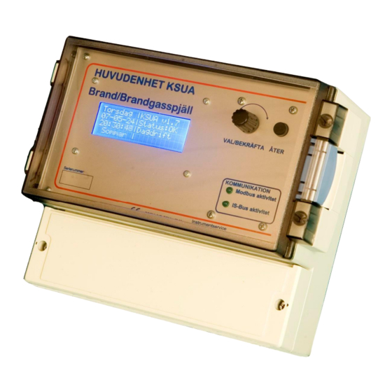
Ext. Fire. Fan 2 output activated when holder is the bayonet type. To remove the fuse, input 9-10 is off. press the holder down and twist anticlockwise. Front panel layout KSUA CONTROL PANEL Fire Dampers SELECT/ENTER BACK COMMUNICATION Modbus Activity... -
Page 7: Menu System
Flashes when a Modbus message is received Encoder for selecting options. Push the knob to Flashes when an SBus message is received select or activate an option. Friday |KSUA V2.0 08-11-09 |Status:OK 08:42:29 |Day mode Winter Operation Status View. - Page 8 If Modbus is used for the exercise, Fire SlvDay =NO this menu should never be used. DAMPER| DMP ITF All outputs and inputs in the KSUA can be TABLE | 4 YVN viewed in real time. SlvDay is a day mode Select|| 5 YVN request from a slave.
- Page 9 SETTINGS slave unit 1. Damper numbers 5 and 6 are in Damper Table slave unit 2, etc. Detector groups · DMP stands for damper number. Fan Relays · I indicate whether the damper is installed. · T is the type either ventilation Select Fan Relays to configure the way the damper or evacuation damper.
- Page 10 All the relays in the various models of KSUC FAN, relay 2 completely follows relay 1. can be connected to the four different relays in CONFIGURE RELAY 2: the KSUA. Menus 18 to 23 are used to change | Func: EVAC FAN the settings. | Await ED open:...
-
Page 11: Troubleshooting
Locking may occur if night mode is indicated system. It can take a lot of work to find out by the KSUA, which then sends a stop signal to what exactly caused the problem. The KSUA the system via fan lock on the FAN 1 output.
Need help?
Do you have a question about the KSUA and is the answer not in the manual?
Questions and answers