
Summary of Contents for Varco HT-Tong HT14
- Page 1 HT-Tong HT-Tong User's Manual User's Manual pn 50006190 Revision -, October 2003 Rev A, December 2004...
- Page 2 © Copyright 2004 Varco LP. All rights reserved. Varco is a registered trademark of Varco I/P reg. U.S. Patent & Trademark Office. This publication is the property of, and contains information proprietary to Varco International, Inc. No part of this publication may be reproduced or copied in any form, or by any means, including electronic, mechanical, photocopying, recording or otherwise, without the prior written permission of Varco IP®.
-
Page 3: Table Of Contents
Table of Contents Chapter 1: General information How to use this manual ............1-5 Special information . - Page 4 Table of Contents Chapter 5: Operations Changing size components ........... . 5-20 Changing dies/inserts .
-
Page 5: Chapter 1: General Information
PERSONAL INJURY. Please understand that these warnings cannot cover all conceivable ways in which service (whether or not recommended by Varco) might be done, or the possible hazardous consequences of each conceivable ways. Anyone using service procedures or tools, whether or not recommended by Varco Systems, must be thoroughly satisfied that neither personal safety nor equipment safety will be jeopardized. -
Page 6: Illustrations
Varco documentation. Safety Requirements Varco equipment is installed and operated in a controlled drilling rig environment involving hazardous situations. Proper maintenance is important for safe and reliable operation. Procedures outlined in Varco manuals are the recommended methods of performing operations and maintenance. -
Page 7: General System Safety Practices
Verify that all components (such as cables, hoses, etc.) are tagged and labeled during assembly and disassembly of equipment to ensure correct installation. Replace failed or damaged components with Varco certified parts. Failure to do so could result in equipment damage or injury to personnel. -
Page 8: Routine Maintenance
Repairs involving welding and/or machining should be performed only by an authorized Varco BJ repair facility. Using a manual tong that has been improperly welded or repaired can cause failure which may result in serious bodily injury or property damage. -
Page 9: Lifting
Limited warranty The warranty will be void if the HT-Tong or parts were either: unauthorized modified, repaired or serviced replacement parts not manufactured by Varco were utilized not properly stored or maintained Design standard The HT-Tong complies with API-7K and with the Directive 98/37/EC (Machinery Directive) - Page 10 General Information 1-10 HT-Tong...
-
Page 11: Specifications, Requirements & Sizes
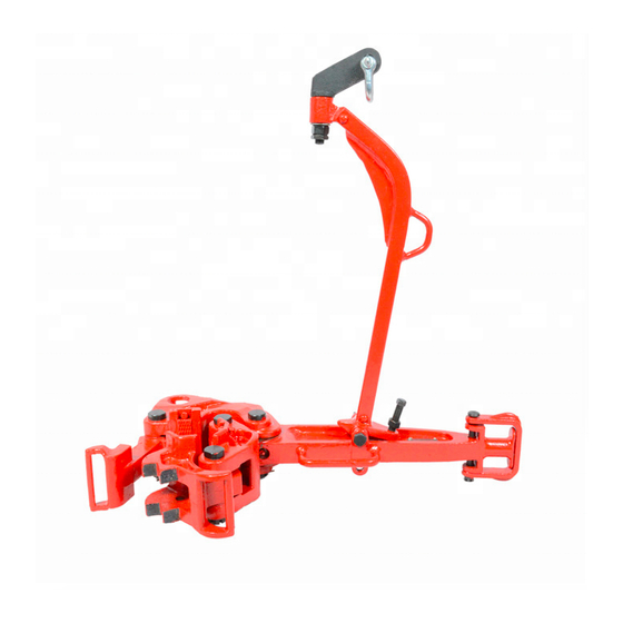
Specifications General specifications Specifications, requirements & sizes General description The HT-Tong is a tool designed for making up and breaking connections of tubular goods, from light tubing to heavy wall pipe and drill collars. There are 7 types, varying in torque capacity from 10,000 to 200,000 Lbs / ft (13,560 - 271,000Nm). -
Page 12: Part Numbers, Ratings & Weights
Specifications Part numbers, ratings & weights Part Type Lug jaw Lug jaw Rating (ft- Part Type Lug jaw Lug jaw Rating (ft- number size (inch) lbs) number size (inch) lbs) HT-200 200506-1 8 - 9 " 200,000 HT-50 200580-8 24 - 25½" 50,000 HT-200 200507-1* 9 - 11... -
Page 13: Chapter 3: Lubrication And Maintenance
Maintenance Lubrication and maintenance CAUTION: Practice safety in all performances of operation and maintenance and use approved safety methods, materials and tools. Keep hands away from any pinch point or undesignated areas; use provided handles for operating manual tongs. Recommended General Purpose EP grease Lube code description Above -20°... -
Page 14: Magnetic Particle Inspection
Degree 1 chaplets Porosity Degree 1 Degree 2 NOTE: Only a Varco BJ authorized repair facility is allowed to remanufacture HT tongs which have indications outside the acceptance criteria. Tests Torque test The HT tongs are torque tested after manufacture or repair to 1.5 times their torque rating. -
Page 15: Maximum Allowable Wear To Maintain 100% Torque Rating
Maintenance Maximum allowable wear to maintain 100% torque rating Tong type Dimension A Dimension B Maximum clearance Maximum clearance (inch) (inch) HT 200 0.045 0.035 HT 100 0.035 0.035 HT 65 0.035 0.035 HT 55 0.035 0.035 HT 35 0.030 0.035 HT 14 0.030... - Page 16 Maintenance 3-16 HT-Tong...
-
Page 17: Chapter 4: Installation And Commissioning
5. The pull line must than be connected to the end of the lever. A back up line, sized to safely withstand the tong torque rating, should in all cases be connected to secure safe operation. 6. A Varco BJ tong pull back can be installed which automatically re-positions the tong for another take-up. 4-17... - Page 18 Installation and Commissioning 4-18 HT-Tong...
-
Page 19: Chapter 5: Operations
Operations Operations WARNING: Keep hands away from any pinch point or undesignated areas; use the handles provided operating the HT tongs. WARNING: Personnel must stay out of working area of tong WARNING: Ensure snub-line-saver with safety line is in place Procedure With the HT Tong positioned and balanced properly, follow the steps outlined below;... -
Page 20: Changing Size Components
Operations Changing size components Changing dies/inserts Procedure 1. Remove the retaining pins by taking out the cotter pin CAUTION: Wear eye protection when removing or replacing inserts to protect against chip fragments 2. A “nifty” tong die slot conditioner and die driver can be used to drive the dies out and recondition the die slots. -
Page 21: Applying Make Up Torque
Operations Applying make up torque Torque is the measurement of the amount of twist applied to two pipes as they are screwed together. The product of the tong arm length L and the line pull F is the measurement of torque, when the tong-arm and the pulling line are at a (90°) angle. Example: ”... -
Page 22: Direction Of Pulling
Operations Direction of pulling NOTE: In below figure the tongs are NOT the back up tongs, but the ones being used for MU/BO. Below images show TOPVIEWS HT35 HT55 Make Up Break Out HT14 HT55 HT100 HT200 Make Up Break Out 5-22 HT-Tong... -
Page 23: Chapter 6: Assembly And Dis-Assembly
Assembly Assembly and dis-assembly Head assembly procedure Procedure 1. Disconnect the head assembly from the lever by removing the hinge pins and lock 2. Disconnect the latch by removing the hinge pin . This allows removal of the latch spring and latch spring plunger. 3. - Page 24 Assembly 6-24 HT-Tong...
-
Page 25: Chapter 7: Trouble Shooting
Troubleshooting Trouble shooting When problems cannot be solved, contact an authorized Varco repair facility Overview possible problems Problem Possible cause Possible solution Tong does not bite Worn die Replace die Check manual for correct Tong not correctly dressed for size... - Page 26 Troubleshooting 7-26 HT-Tong...
-
Page 27: Summary Of Risk Assessment
Appendix Appendixes Summary of risk assessment Identified potential hazard Point of failure Result Chain/cable/pull line This may cause the tong rotate uncontrollable, Breaking of chain/cable/pull line overtensioned hitting everything in it's way. Chain/cable/pull line Breaking of chain/cable/pull line Cable releases energy, flying all over the place overtensioned The tong being used may break because of too Pulling too hard relative to tong... -
Page 28: General Conclusions
Appendix Identified potential hazard Point of failure Result SYSTEM Tong may slip and make unexpected Missing dies Missing cotter pin/retainer pins movement Coupling may not be made up properly resulting of loosing pipe Tong may slip and make unexpected Breaking dies Overload/wear movement Coupling may not be made up properly... -
Page 29: Torque Values (Us) For Bolts
Appendix Torque values (US) for bolts Bolts Lubricated with Light Machine Bolts lubricated with Anti-seize Oil Grade 8 compound Grade 8 Dia. Threads per Min. Torque Max. Clamp Min. Torque Max. Clamp inch (ft lb) Torque force (ft lb) Torque force (ft lb) (lb) -
Page 30: Torque Values (Metric) For Bolts
Appendix Torque values (metric) for bolts Bolts Lubricated with Light Bolts lubricated with Anti-seize Machine Oil Grade 8 compound Grade 8 Threads per Min. Max. Clamp Min. Max. Clamp meter inch Torque Torque force Torque Torque force (Nm) (Nm) (Nm) (Nm) Coarse Thread Series, UNC ”... -
Page 31: Chapter 9: Drawings And Parts Break Down
Drawings Drawings and Parts Break Down Added parts jaw assemblies NOTE: In the exploded views on the following pages, several parts, especially the jaw assemblies, are not showed. In this chapter you will find these parts. TOPVIEW Handle bolt Flat washer Plastic safety cap Grip hose Plastic safety cap... -
Page 32: Ht-14 Additional Parts
Drawings HT-14 additional parts Per grip point Name Part number Handle bolt 50010-52-C8 Grip hose 203439 Nut, self locking 51850-10-C Plastic safety cap 250369 Washer, flat 50810-R-C HT-35 additional parts Per grip point Name Part number Handle bolt 50010-52-C8 Handle bolt (long jaw) 50010-60-C8 Grip hose 203439... -
Page 33: Ht-100 Additional Parts
Drawings HT-100 additional parts Per grip point Name Part number Handle Bolt 50010-60-C8 Grip hose 203439 Nut, self locking 51850-10-C Plastic safety cap 250369 Washer flat 50810-R-C HT-200 additional parts Per grip point Name Part number Handle bolt 50010- 76-C8 Grip hose 203439 Nut, self locking... -
Page 34: Parts Lists And Exploded Views
Drawings Parts lists and exploded views Parts list HT 14 manual tong Item. No No. Req Description Part no. Item. No No. Req Description Part no. Lever ass’y 200641-1 Plunjer pin 23922 Lever (note 1) Grease fitting 53201 Tong line pin retainer 23918 Safety line bolt 939099-204... -
Page 35: Exploded View Ht-14
Drawings Exploded view HT-14 9-35 HT-Tong... -
Page 36: Parts List Ht 35 Manual Tong
Drawings Parts list HT 35 manual tong Item.No No. Req Description Part no. Item. No No. Req Description Part no. Long lever ass’y 200621-1 Latch ass’y 200626-1 Long lever (note 1) Latch (note 1) Short lever ass’y 200622-1 Hinge pin nut 200632 Short lever (note 1) -
Page 37: Exploded View Ht-35
Drawings Exploded view HT-35 9-37 HT-Tong... -
Page 38: Parts List Ht 55 Manual Tong
Drawings Parts list HT 55 manual tong Item. No No. Req Description Part no. Item. No No. Req Description Part no. Long lever ass’y 200561-1 Latch jaw ass’y 200566-1 Long lever (note 1) Latch jaw (note 1) Short lever ass’y 200562-1 16402-6 Short lever... - Page 39 Drawings Exploded view HT55 9-39 HT-Tong...
-
Page 40: Part List Ht 65 Manual Tong
Drawings Part list HT 65 manual tong Item No No. Req Description Part no. Item No No. Req Description Part no. Lever ass’y 200541-1 Latch spring 24525 Lever (note 1) Hinge pin 200550 Tong line retainer 24529 Hinge pin nut 24528 Tong line retainer bolt 24249... -
Page 41: Exploded View Ht-65
Drawings Exploded view HT-65 9-41 HT-Tong... -
Page 42: Parts List Ht100 Manual Tong
Drawings Parts list HT100 manual tong Item. No No. Req Description Part no. Item. No No. Req Description Part no. Lever ass’y 200661-1 Latch spring 24525 Lever (note 1) Hinge pin 200204 Tong line retainer 24529 Hinge pin nut 24528 Tong line retainer bolt 24249 Cotter pin... -
Page 43: Exploded View Ht-100
Drawings Exploded view HT-100 9-43 HT-Tong... -
Page 44: Parts List Ht 200 Manual Tong
Drawings Parts list HT 200 manual tong Item. No No. Req Description Part no. Item. No No. Req Description Part no. Lever ass’y 200501-1 Opt. Air lift ass’y 30041-1 Lever (note 1) Range 6"-7 " Tong line retainer 24529 Lug jaw ass’y 200506-SP Tong line retainer bolt 24249... -
Page 45: Exploded View Ht-200
Drawings Exploded view HT-200 9-45 HT-Tong... -
Page 46: Parts List Ht 50 Casing Head Assemblies
Drawings Parts list HT 50 casing head assemblies Fig. A Fig. B Fig.C Fig. D Fig.E Fig F Fig G Fig.H 200580-1 200580-2 200580-3 200580-4 200580-5 200580-6 200580-7 200580-8 Ref. Description No. req. No. req. No. req. No. req. No. req. No. - Page 47 Drawings Fig I. Fig J Fig. K Fig. L Fig. M Fig. N Fig.O 200600-1 200600-2 200600-3 200600-4 200600-5 200600-6 200600-7 Ref. Description No. req. No. req. No. req. No. req. No. req. No. req. No. req. Part no. 16402-6 Handle bolt 50010-54-C8 50510-C...
-
Page 48: Casing Head Assemblies Overview
Drawings Casing head assemblies overview 9-48 HT-Tong... -
Page 49: Critical Area Drawings
Drawings Critical area drawings 9-49 HT-Tong... - Page 50 Drawings 9-50 HT-Tong...
- Page 51 Drawings 9-51 HT-Tong...
- Page 52 Drawings 9-52 HT-Tong...
- Page 53 Drawings 9-53 HT-Tong...
- Page 54 Drawings 9-54 HT-Tong...
- Page 55 Drawings 9-55 HT-Tong...
- Page 56 Drawings 9-56 HT-Tong...
Need help?
Do you have a question about the HT-Tong HT14 and is the answer not in the manual?
Questions and answers