
Summary of Contents for Burkhard Reuter RLA4
- Page 1 Specifications and Operator's Manual of Antenna RLA4 Edition: 1.5 Created: 11.01.2019 Konstruktion & Musterbau Burkhard Reuter Ziegelstraße 54 06862 Dessau-Roßlau...
-
Page 2: Specifications
Compliance: CE according to DIN EN 55013, EN 55020, EN 60065 RoHS / WEEE directive, ear reg. nr. 27676700 Specifications are subject to change! K & M Burkhard Reuter EDITION DATE NAME Page RLA4 8/19/19 B. -
Page 3: Safety Information
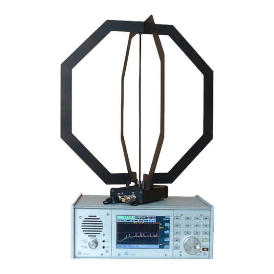
Use only soft, lint-free and dry cloths for cleaning the device! In case of persistent soiling, never use solvents! At most, a slight moistening of the cleaning rag with distilled water is appropriate! Make sure that moisture never penetrates into the device! K & M Burkhard Reuter EDITION DATE... - Page 4 The RLA4A-C's connectors and switches When operating the RLA4 via the normal circuit as a loop, the loop is active from the front right (via jack "RX") to the rear left. Its main reception direction lies in this direction (in the loop plane, corresponds to 0°).
- Page 5 The previous description refers to the supply of the antenna directly to the housing with 12 V DC. The RLA4 can also be supplied with operating voltage via the RF cable (remote supply). The local supply via the DC socket should then be removed. The switch is no longer active and doesn't light up, even if the...
- Page 6 In most cases, there is a matching control byte for the RLA4 for exact positioning of the zero point in the desired direction. However, this is different for varying operating conditions (voltage, temperature).
- Page 7 4D – 4F. Assembly and disassembly The RLA4 is usually shipped in partially disassembled condition. In this condition, it can be packed and transported to save space. For mobile use, disassembly for transportation is ideal. Especially the RLA4F can be assembled very easily and without tools. Proceed as follows: - Unscrew the knurled nuts from the connecting bolts of the amplifier and the upper side of the threaded rod (if unscrewed during transport, so as not to lose them).
- Page 8 Connection of the steel strips with the threaded rod The RLA4 versions D and E possess individual elements made of printed circuit board material (FR4) instead of the stainless steel loops. Each closed loop consists of 2 elements, each of which must be screwed on using short M4 screws (Torx) and a spring washer.
- Page 9 If this requires a great deal of effort, or if the bolt loosens, the amplifier must be dismantled and the internal screwed connections must be re- fastened. K & M Burkhard Reuter EDITION DATE...