
Related Manuals for SKI AccuFlo Zero

Summary of Contents for SKI AccuFlo Zero
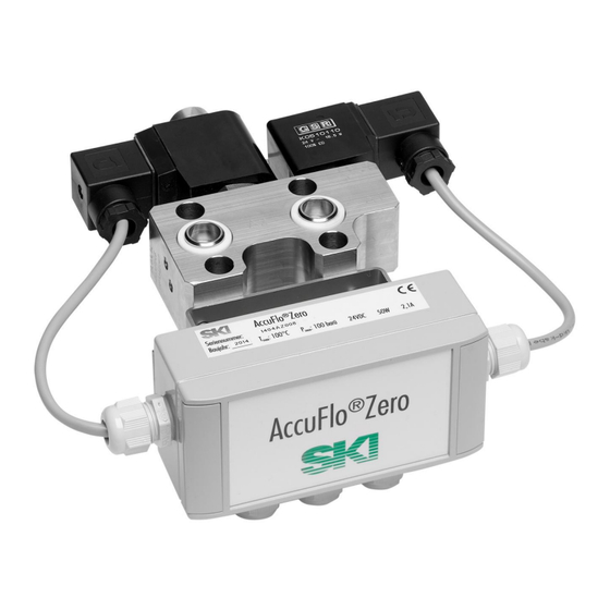
- Page 1 ® AccuFlo Zero Automatic Zero-Point Calibration For Differential Pressure Transmitters Installation and Operating Instructions...
-
Page 2: Table Of Contents
® Zero – Installation and Operating Instructions AccuFlo Attention: Please refer to the warning information on page 3 and 4 before commissioning! Content General information ...................... 3 Safety information ..........................3 Qualified personnel ..........................3 Further information ..........................3 Special warnings ..........................4 Correct usage ........................ -
Page 3: General Information
® Zero – Installation and Operating Instructions AccuFlo 1 General information 1.1 Safety information This device left the factory free from safety problems. In order to maintain this status and to ensure safe operation of the device, please observe the safety information and warnings contained in this instruction. ... -
Page 4: Special Warnings
® Zero – Installation and Operating Instructions AccuFlo 1.4 Special warnings Exceeding pressure: Appropriate measures are to be taken to secure that the allowed operation pressure according to the stamp on the type plate is not exceeded. Normal usage: On acceptance and within the required control intervals, a compression test under overpressure and a leakage test have to be conducted for the whole system. -
Page 5: Correct Usage
® Zero – Installation and Operating Instructions AccuFlo 2 Correct usage ® The AccuFlo Zero is used for automatic zero-point calibrations. The device may only be used for the purposes specified in these instructions. All changes to the device are the sole responsibility of the user if they are not explicitly stated in these instructions,. -
Page 6: Inspection Of Incoming Goods
® Zero – Installation and Operating Instructions AccuFlo 4 Inspection of incoming goods Please check the scope of supply for the following items: ® AccuFlo Zero ® AccuFlo Zero 2. Threaded rods and screw nuts: 7/16-UNF or M10 (according to the transmitter) for assembling of the system. -
Page 7: Electrical Connections And Assembling
® Zero – Installation and Operating Instructions AccuFlo 5 Electrical connections and assembling ® Installation of the AccuFlo Zero ® The AccuFlo Zero has to be installed between the valve manifold and the differential pressure transmitter (see Figure 1). ® Figure 1: Assembled AccuFlo Zero ®... -
Page 8: Electrical Connections
® Zero – Installation and Operating Instructions AccuFlo ® Figure 2: Metal block of the AccuFlo Zero ® Then the AccuFlo Zero is pushed upon the threaded rods. Now the seals are laid in the grooves of the valve manifold (or existing ones are replaced). The valve manifold is pushed upon the thread rods as well. -
Page 9: Status Relay
® Zero – Installation and Operating Instructions AccuFlo Status relay ® The AccuFlo Zero includes two status relays which may offer following signals: ® The relay “in operation” issues signal “1” if the AccuFlo Zero is switched on and the transmitter is identified. In ®... - Page 10 ® Zero – Installation and Operating Instructions AccuFlo ® Power supply of the AccuFlo Zero: Table 1: Jumper "J1" set/closed Terminal Description +24 V Power supply 24 V DC / 2 A ® Connection between the AccuFlo Zero and the differential pressure transmitter: Table 2: Connection to the transmitter Terminal Terminal in transmitter...
- Page 11 ® Zero – Installation and Operating Instructions AccuFlo ® Option 2: +24-V-signal from AccuFlo Zero to the control station mode as group message Remove/open jumper „J2“. Connect terminal “E4” with “F4”! Table 5: Relay output - option 2: Terminal Description Signal „Ready and Calibration Successful”...
- Page 12 ® Zero – Installation and Operating Instructions AccuFlo If necessary: external triggering of the zero-point calibration Table 8: Signal „start zero-point calibration“ from the control station to the AccuFlo®Zero Terminal Description ® GND of the AccuFlo Zero If GND is connected to „G3“, the zero-point GND = Start calibration calibration is initiated.
-
Page 13: Commissioning
® Zero – Installation and Operating Instructions AccuFlo 6 Commissioning General procedure If all components are connected, please switch on the power. The control of the display of the differential ® pressure transmitter shows the operational state of the transmitter. A LED in the AccuFlo Zero (see Figure 3, page 9) will light up after short time and indicate that the device is powered. -
Page 14: Delete A Correction Of Positioning
® Zero – Installation and Operating Instructions AccuFlo Delete a correction of positioning If no correction of positioning is needed, it may be deleted from the system. This is reasonable for example for the use of the transmitter on a different measure point after demounting. Procedure: ®... -
Page 15: Led Lights Up Permanently
® Zero – Installation and Operating Instructions AccuFlo LED lights up permanently After switching on the LED lights up permanently for more than one minute or errors occur during the zero-point calibration: Is the connection to the transmitter is faultless? ... -
Page 16: Technical Data
® Zero – Installation and Operating Instructions AccuFlo 9 Technical data General information Automatic zero-point calibration Cycle length between calibrations Configurable at order (factory setting: 24 h) Temperature trigger Configurable at order (factory setting: 10 K temperature difference between last calibration) Length 30 s Maintaining of analog output signal... -
Page 17: Electrical Data
„ready“ (may be grouped up to one signal) Interfaces ® External RS485-Bus AccuMind (flow computer unit of SKI GmbH) Configuration Permanent bridges Basic functions are to be chosen by using jumpers. Short-time bridges A manual zero-point calibration or a correction of... -
Page 18: Declaration Of Confirmity
® Zero – Installation and Operating Instructions AccuFlo 10 Declaration of Confirmity ® Installation and operating instructions AccuFlo Zero... - Page 19 ® Zero – Installation and Operating Instructions AccuFlo ® Installation and operating instructions AccuFlo Zero...
- Page 20 Hanns-Martin-Schleyer-Str. 22 D-41199 Mönchengladbach Tel: +49 (0) 2166/62317-0 Web: www.ski-gmbh.com E-Mail: info@ski-gmbh.com Registered trademarks and logos are the property of their owners. Subject to technical changes. The illustrations may contain optional installations. BA-AccuFloZero-en-L-1643.docx ® Installation and operating instructions AccuFlo Zero...
Need help?
Do you have a question about the AccuFlo Zero and is the answer not in the manual?
Questions and answers