Table of Contents
Advertisement
Quick Links
PREP STEP: Jig Assembly
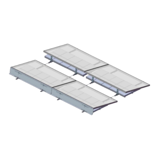
Step 2 - Layout Array on Roof
Rail and
Feet
Assembly Instructions for
TABLE OF CONTENTS
Install Confidence
1010 B Street, Suite 400 - San Rafael, CA 94901
415-925-9650 - www.sunlink.com
Pages 1-2
Page 3
Page 4
Page 5
Page 6
Page 7
Page 8
Page 9
Page 10
Pages 11 - 12
Page 13
North Strut
South
Clip
Ballast
Beam
Deflector
T-Beam
(double ballast only)
Advertisement
Table of Contents

Summary of Contents for SUNLINK Precision-Modular RMS
-
Page 1: Table Of Contents
Assembly Instructions for Precision-Modular RMS TABLE OF CONTENTS Notices and Safety Precautions Pages 1-2 Component and Tool Quick Reference Page 3 PREP STEP: Jig Assembly Page 4 PREP STEP: Component Preassembly Page 5 Step 1 – Assemble Racking Structure Page 6 Step 2 –... -
Page 2: Precision-Modular Rms
Ballast – Precision-Modular RMS is a ballasted system, meaning that its primary means of retention on the roof is the weight of the system. The ballast is engineered to work with the environmental and structural constraints of each project, therefore the number and location of ballast units shown on the engineering documentation needs to be strictly adhered to. - Page 3 Report any distortion in the assembly to SunLink. Array substructure supports should be in full contact with the roof or the ground. Any indication of uneven distribution of weight should be evaluated and corrected before continuing with electrical finishing.
-
Page 4: Component And Tool Quick Reference
Assembly Instructions for Precision-Modular RMS Component and Tool Quick Reference COMPONENTS RAIL ASSEMBLY SOUTH CLIP DEFLECTOR (Part #s 20-0001-XXX & 62-0003-001) Part # 21-0001-001 (5/16”) (Part # 22-000X-001) 21-0001-002 (1/4”) RAIL LINK ASSEMBLY SIDE LINK BALLAST BEAM Part # 23-0001-001 +Carriage Bolts Part # 23-0003-001 Part # 24-0001-001 (62”) - Page 5 PREP STEP – JIG ASSEMBLY One of the best features of Precision-Modular RMS is that it uses a project module and two simple locator attachments to create a perfectly sized, foolproof project jig. By using a module as the foundation for the jig, measurements are exact and there is no need for any measuring or aligning on the roof.
-
Page 6: Prep Step: Component Preassembly
A. Mount 2 carriage bolts and nuts on each Rail Link, using the correct hole option (there are four) to Registration tabs correspond to the proper row space setting. B. See SunLink layout for row spacing and corresponding correct hole option. North end bolt Beam Clip Assembly A. -
Page 7: Step 1 - Assemble Racking Structure
Assembly Instructions for Precision-Modular RMS Step 1 – Assemble Racking Structures Note that the Racking Structure assembly process described below can be completed off-roof or off-site in a controlled environment at waist height. A. Place two Rail assemblies on the Jig (as created in the Prep Step on page 4) so that the south edge registers against the South Rail Locator. - Page 8 Step 2 – Layout Racking Structures on Roof A. Position each Racking Structure (as created on Page 6 or in Appendix B) on the roof according to the SunLink layout. B. Engage Rail Links on the south end of the previous row by sliding them into the Rail slot of the new row until the registration tabs stop against the Rail.
-
Page 9: Step 3 - Install Modules And Deflectors
Assembly Instructions for Precision-Modular RMS Step 3 – Install Modules and Deflectors A. Use hex head cap screw and nut to attach 2 South Clips to the south side of each PV module using the same mounting holes as used to construct the Jig (on page 4) to ensure proper spacing. -
Page 10: Appendix A - Alternative Configurations
Assembly Instructions for Precision-Modular RMS Appendix A – Alternative Configurations Assemble Racking Structure for Double Row Ballast A. Follow all instructions to assemble Racking Structure from Step 1 on page 6, with the exception of Step C. B. Instead of Step C, register the second Ballast Beam against the outside edge of the North Rail Locators (12x12 Ballast). - Page 11 Assembly Instructions for Precision-Modular RMS Appendix A – Alternative Configurations Install Outriggers A. Assemble outriggers as you would all other north row units with double row Ballast. Place the South end of the rail with standard configuration. B. Include an extra pair of feet placed 1-2 inches from the North edge.
-
Page 12: Appendix B - Grounding Recommendations
Canadian Electrical Code CSA C22.1 - Latest Revisions and local codes and ordinances. Precision Modular RMS is to be mounted over a fire resistant roof covering rated for the application. Precision-Modular RMS is not meant for sloped roofs where the slope is greater than 1 ½”:12”... -
Page 13: Appendix C - Wire Management Recommendations
Assembly Instructions for Precision-Modular RMS Appendix C – Wire Management Recommendations The following guidelines suggest how to string modules together and dress wire bundles for home runs. Stringing can be done in the E-W or N-S direction. Wire bundles or conduit can be carried in the E-W direction under the modules or in front of the deflector. - Page 14 North/South or East/West directions (not supplied). Ex: Wiley clips (ACC-F90-1) C. Attach SunLink Wire Support Clips (Part # 69- 0001-001, included for North rows – additional may be ordered separately) to North Strut. D. Fasten wire bundles to each Wire Support Clip with a zip-tie (not supplied).
-
Page 15: Appendix D - Class A Fire Rating
On East/West edges of the array, each module must have at least two ballast blocks placed at the outer edge. Note: East/West ballast arrangements are indicated per the SunLink drawing set. Please refer to these documents for detailed placement.
Need help?
Do you have a question about the Precision-Modular RMS and is the answer not in the manual?
Questions and answers