Table of Contents
Advertisement
Quick Links
Advertisement
Table of Contents

Summary of Contents for MOBILTEX CorTalk SPI1
- Page 1 Installation and Operating Instructions SPI1 corTalk® Portable & Stationary Interrupters Portable Stationary Print Date: January 17, 2019 TITLE: MOBILTEX® DATA LTD. Installation and Operating Instructions Calgary, Alberta DOCUMENT NO.: SHEET: REV: SPI1-MAN-001 1 of 57 1.14...
- Page 2 RESTRICTED PROPRIETARY INFORMATION ® This information disclosed herein is the exclusive property of Mobiltex Data Ltd. and is not to be disclosed without ® the written consent of Mobiltex Data Ltd. No part of this publication may be reproduced or transmitted in any form or by any means including electronic storage, reproduction, execution or transmission without the prior written consent ®...
-
Page 3: Table Of Contents
Cleaning ............................... 43 Battery Life ..............................43 Servicing ..............................43 Relay Type Encoding ............................44 Cable Diagrams ............................... 45 Specifications ..............................57 TITLE: MOBILTEX® DATA LTD. Installation and Operating Instructions Calgary, Alberta DOCUMENT NO.: SHEET: REV: SPI1-MAN-001 3 of 57... - Page 4 Figure 31 corTalk® Portable Interrupter Configuration Menu Page 1 ................ 34 Figure 32 corTalk® Portable Interrupter Configuration Menu Page 2 ................ 35 Figure 33 SPI1Config Screen Shot ..........................39 TITLE: MOBILTEX® DATA LTD. Installation and Operating Instructions Calgary, Alberta DOCUMENT NO.:...
- Page 5 Table 3 SSR1 Ring Lug Circuits ..........................19 Table 4 SPI1 Stationary Interrupter Power/Relay Control Cable Pinout ..............20 Table 5 Relay Type Encoding Bits ..........................44 TITLE: MOBILTEX® DATA LTD. Installation and Operating Instructions Calgary, Alberta DOCUMENT NO.: SHEET:...
-
Page 6: Introduction
SPI1 Portable & Stationary Interrupter products. This document version applies to SPI1 devices that are equipped with version 1.27 firmware or higher. If your SPI1 ® has firmware with a lower version, some menu items and features may differ. Please contact Mobiltex for firmware updates. -
Page 7: Component Identification And Descriptions
The SPI1 may be secured by installing pad locks (not provided) through the two sets of lock loops. Figure 1 Top Front View of SPI1 Portable Interrupter TITLE: MOBILTEX® DATA LTD. Installation and Operating Instructions Calgary, Alberta DOCUMENT NO.:... -
Page 8: Figure 2 Front And Back Views Of Spi1 Stationary Interrupter
Figure 4 shows the dimensions of the mounting bracket provided with the SPI1 Stationary Interrupter. The plate may be attached to the SPI1 in either a top or bottom mount configuration. TITLE: MOBILTEX® DATA LTD. Installation and Operating Instructions Calgary, Alberta DOCUMENT NO.:... -
Page 9: Figure 4 Spi1 Stationary Interrupter Mounting Bracket Dimensions
Figure 4 SPI1 Stationary Interrupter Mounting Bracket Dimensions Additional accessories are available for alternate mounting applications. Figure 5 shows the SPI1 Stationary Interrupter fitted with an optional RAM mount (Mobiltex P/N H16550B101U). TITLE: MOBILTEX® DATA LTD. Installation and Operating Instructions Calgary, Alberta DOCUMENT NO.:... -
Page 10: Figure 5 Spi1 Stationary Interrupter Optional Ram Mount
Figure 5 SPI1 Stationary Interrupter Optional RAM Mount TITLE: MOBILTEX® DATA LTD. Installation and Operating Instructions Calgary, Alberta DOCUMENT NO.: SHEET: REV: SPI1-MAN-001 10 of 57 1.14... -
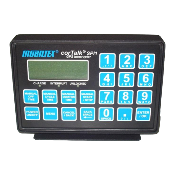
Page 11: Figure 6 Spi1 Keypad And Lcd
5 minutes during an interruption cycle. Interruption is always disabled if the UNLOCKED light is lit. An interruption cycle that has been interrupted by loss of GPS lock will auto-resume upon re-acquisition of the GPS signal. Figure 6 SPI1 Keypad and LCD TITLE: MOBILTEX® DATA LTD. Installation and Operating Instructions Calgary, Alberta DOCUMENT NO.: SHEET:... -
Page 12: Figure 7 Side View Of Spi1 Portable Interrupter
Interrupter. Visible are the protection caps which guard against dust and moisture entering the SPI1 external connectors when the unit is not in use. For easy reference, the connectors are labelled A through E. Figure 7 Side View of SPI1 Portable Interrupter TITLE: MOBILTEX® DATA LTD. Installation and Operating Instructions Calgary, Alberta DOCUMENT NO.:... -
Page 13: Figure 8 Back View Of Spi1 Stationary Interrupter
SPI1 Portable Interrupter. The pinout of the communications connector (D) is shown in Table 1. Table 2 shows the pinout of the relay connectors (A, B, C). TITLE: MOBILTEX® DATA LTD. Installation and Operating Instructions Calgary, Alberta DOCUMENT NO.:... -
Page 14: Figure 10 Spi1 External Connectors
Charger/60Hz Reference AC Input (Reference Capability On Port A Only) Charger/60Hz Reference AC Input (Reference Capability On Port A Only) ® RELAYSNS Relay Type Detect Line (For Use With Mobiltex Provided Relays) Table 2 SPI1 Relay Connector Pinout Figure 10 SPI1 External Connectors Figure 11 and Figure 12 show the charging cables for the SPI1 Portable Interrupter. -
Page 15: Figure 11 Spi1 Ac Charge Cable
The cable may be used to load new firmware into the SPI1 by attaching the DE-9S connector to the serial port on a PC and using the ‘SPI1Loader.exe’ application. This cable may also be used for configuration of general parameters and schedules using the PC-based utility ‘SPI1Config.exe’. TITLE: MOBILTEX® DATA LTD. Installation and Operating Instructions Calgary, Alberta DOCUMENT NO.:... -
Page 16: Figure 13 Spi1 Programming Cable
Figure 15 shows the GPS antenna used with the SPI1 Stationary Interrupter. The antenna has a 3 meter cable attached that is terminated with an SMA connection. The SMA connector must be threaded on the GPS antenna port on the rear of the SPI1 Stationary Interrupter. TITLE: MOBILTEX® DATA LTD. Installation and Operating Instructions Calgary, Alberta DOCUMENT NO.:... -
Page 17: Figure 15 Spi1 Stationary Interrupter Gps Antenna
P/N W16400CPI03) used to connect the SPI1 Portable ® Interrupter to the MSR2 relay or directly to a rectifier with a Mobiltex interruption port already hardwired in. The cable is symmetric, so either end can be plugged into the SPI1 or the MSR2. The connectors on the cable and SPI1/MSR2 form a waterproof connection when mated. -
Page 18: Figure 17 Msr2 External Connectors
8A at 250VAC/150VDC max. The MSR2 is internally protected with a 10 Amp slow blow 5mm x 20mm ® fuse. Replacement fuses are available from Mobiltex as part number F0131110A00 (Littelfuse part number 218010HXP). The MSR2 is connected to the device requiring interruption through two clip-on leads. -
Page 19: Figure 18 Solid State Relay (Ssr1) Connections
Line power input connected to relay contacts. Black Line Out (L1 Switched) Switched line power output from relay contacts. Table 3 SSR1 Ring Lug Circuits TITLE: MOBILTEX® DATA LTD. Installation and Operating Instructions Calgary, Alberta DOCUMENT NO.: SHEET: REV: SPI1-MAN-001 19 of 57 1.14... -
Page 20: Figure 19 Spi1 Stationary Interrupter Power And Relay Control Cable
® Figure 19 shows the 1.5 meter (10 feet) long cable (Mobiltex P/N W16400CPI10) used to connect the SPI1 Stationary Interrupter to a rectifier. The connections to the rectifier are provided as bare, un-terminated wires. The following connections are available at the end of the cable:... -
Page 21: Figure 20 Hpr2 Dc-Only 100A High Power Relay
Under this situation, if the rectifier output is higher than approximately 10V, the SPI1 will be powered from the HPR2. Figure 20 HPR2 DC-Only 100A High Power Relay TITLE: MOBILTEX® DATA LTD. Installation and Operating Instructions Calgary, Alberta DOCUMENT NO.:... -
Page 22: Figure 21 Hpr2 Attachment Cables
The blue banana jack connection should be attached to source being interrupted. For example, if the negative leg of the DC output on a TITLE: MOBILTEX® DATA LTD. Installation and Operating Instructions Calgary, Alberta DOCUMENT NO.:... -
Page 23: Figure 23 Hpr1 Ac/Dc 50A High Power Relay
Under this situation, if the rectifier output is higher than approximately 10V, the SPI1 will be powered from the HPR1. Figure 23 HPR1 AC/DC 50A High Power Relay Figure 24 HPR1 Attachment Cables TITLE: MOBILTEX® DATA LTD. Installation and Operating Instructions Calgary, Alberta DOCUMENT NO.: SHEET:... -
Page 24: User Interface Summary
Off Time Indicates The Off Time Of The Currently Active Schedule. OFF TIME (ms) Manual Interruption Off Time MANUAL (1ms Steps, Range 1 To Cycle Time) TIME TITLE: MOBILTEX® DATA LTD. Installation and Operating Instructions Calgary, Alberta DOCUMENT NO.: SHEET: REV: SPI1-MAN-001 24 of 57... - Page 25 Return To Previous Menu/ / BACK Cancel Current Edit Field BACK Backspace In Current Edit Field SPACE ENTER Complete/Accept Current Edit Field / OK TITLE: MOBILTEX® DATA LTD. Installation and Operating Instructions Calgary, Alberta DOCUMENT NO.: SHEET: REV: SPI1-MAN-001 25 of 57 1.14...
- Page 26 * , - … Numeric/Text Entry Keys ? ! : TITLE: MOBILTEX® DATA LTD. Installation and Operating Instructions Calgary, Alberta DOCUMENT NO.: SHEET: REV: SPI1-MAN-001 26 of 57 1.14...
-
Page 27: Figure 25 Cortalk® Portable Interrupter Menus
[2]TZONE [5]FORMAT [3]GPS T [6]DATALOG [3]S3 [6]S6 [3]OFFSET [6]BKLIGHT Continue to page 28. Continue to page 29. Continue to page 34. TITLE: MOBILTEX® DATA LTD. Installation and Operating Instructions Calgary, Alberta DOCUMENT NO.: SHEET: REV: SPI1-MAN-001 27 of 57 1.14... -
Page 28: Figure 26 Cortalk® Portable Interrupter Status Menu
GPS TIME STATUS The LM field is a diagnostic field, the value of which may ® SAT: 06* LM: 052 be request by Mobiltex technical support. TIME: 18:42:35 UTC The TIME and DATE fields indicate the current UTC time DATE: 2005/03/03 as received from the GPS system. -
Page 29: Figure 27 Cortalk® Portable Interrupter Scheduler Menu
RNG field shows the current meter range for the datalogger input. *Datalogger Status screen only available on SDL1 equipped devices. Figure 27 corTalk® Portable Interrupter Scheduler Menu Page 1 TITLE: MOBILTEX® DATA LTD. Installation and Operating Instructions Calgary, Alberta DOCUMENT NO.: SHEET: REV:... -
Page 30: Figure 28 Cortalk® Portable Interrupter Scheduler Menu
HH:MM. 1=YES,0=NO SCHEDULE ENABLED Enables/disables current schedule. 1=YES,0=NO Figure 28 corTalk® Portable Interrupter Scheduler Menu Page 2 TITLE: MOBILTEX® DATA LTD. Installation and Operating Instructions Calgary, Alberta DOCUMENT NO.: SHEET: REV: SPI1-MAN-001 30 of 57... - Page 31 0s into the minute, the rectifier will turn back on for a duration of ‘cycle time 1=YES,0=NO – off time’, then be followed by the off portion of the cycle. TITLE: MOBILTEX® DATA LTD. Installation and Operating Instructions Calgary, Alberta DOCUMENT NO.: SHEET: REV:...
-
Page 32: Figure 29 Cortalk® Portable Interrupter Scheduler Menu
This parameter can 1=±20Vpk be set to 0 for +/-6Vpeak, 1 for +/-20Vpeak, 2 for +/- 60Vpeak, and 3 for +/-75Vpeak. 2=±60Vpk TITLE: MOBILTEX® DATA LTD. Installation and Operating Instructions Calgary, Alberta DOCUMENT NO.: SHEET: REV:... -
Page 33: Figure 30 Cortalk® Portable Interrupter Scheduler Menu
Enable/disable a 60Hz digital filter on the current schedule. The digital filter in the datalogger will suppress 60Hz noise by an additional 27dB over the 1=YES,0=NO hardware filtering (54dB). TITLE: MOBILTEX® DATA LTD. Installation and Operating Instructions Calgary, Alberta DOCUMENT NO.: SHEET: REV:... -
Page 34: Figure 31 Cortalk® Portable Interrupter Configuration Menu
[3]OFFSET [6]BKLIGHT The SPI1 must be programmed with a relay type that encodes the necessary information to drive a particular ® relay in the correct manner. All Mobiltex provided RELAY TYPE relays will have a relay type printed on the label. -
Page 35: Figure 32 Cortalk® Portable Interrupter Configuration Menu
FACTORY DEFAULTS Reverts all configuration and scheduler parameters back to factory default values. ENTER/OK TO CONTINUE CANCEL/BACK TO ABORT TITLE: MOBILTEX® DATA LTD. Installation and Operating Instructions Calgary, Alberta DOCUMENT NO.: SHEET: REV: SPI1-MAN-001 35 of 57... -
Page 36: Basic Operation
To allow for this, the SPI1 must be programmed with a relay type that encodes the necessary ® information to drive a particular relay in the correct manner. All Mobiltex provided relays will have a relay type printed on the label. -
Page 37: Offset
Attach cable W16400CPI01, W16400CPI02, or W16400CPI03 between one of the relay ports on the SPI1 and the matching port on the interruption relay or rectifier. If attaching to a rectifier that is equipped to provide 12VAC TITLE: MOBILTEX® DATA LTD. Installation and Operating Instructions Calgary, Alberta DOCUMENT NO.:... -
Page 38: Manual Interruption
60s, otherwise synchronized interruption may not occur. Some manufacturers’ interrupters re-synchronize at the top of the minute, top of the hour or top of the day. The TITLE: MOBILTEX® DATA LTD. Installation and Operating Instructions Calgary, Alberta DOCUMENT NO.:... -
Page 39: Polarization Operation
Microsoft Windows 2000/XP/2003/Vista operating system and have an unused RS-232 serial port). SPI1Config presents a graphical user interface (GUI) that simplifies the entry of parameters into the SPI1. Figure 33 shows the main screen: Figure 33 SPI1Config Screen Shot TITLE: MOBILTEX® DATA LTD. Installation and Operating Instructions Calgary, Alberta DOCUMENT NO.: SHEET:... -
Page 40: Firmware Updates
Individual schedules are chosen by selecting the appropriate tab in the GUI. ® The relay information may be changed in one of two ways. First, the relay type, as stamped on Mobiltex provided relays, can be entered directly into the ‘Relay Type’ field. When a different field is selected, the ‘Voltage’, ‘Contacts’, ‘Close Dwell’, and ‘Open Dwell’... -
Page 41: Optional Datalogger Operation
Setting the range too low results in over ranging the input analog to digital converter. This parameter can be set to 0 for +/-6Vpeak, 1 for +/-20Vpeak, 2 for +/-60Vpeak, and 3 for +/-150Vpeak. TITLE: MOBILTEX® DATA LTD. Installation and Operating Instructions Calgary, Alberta DOCUMENT NO.:... -
Page 42: Text Notes
**Important**, after completing data retrieval, remove the USB cable from the SPI1. The SDL1 will not perform any logging operations while the USB cable is attached to the PC. TITLE: MOBILTEX® DATA LTD. Installation and Operating Instructions Calgary, Alberta DOCUMENT NO.:... -
Page 43: Maintenance
After the counter exceeds a value of 12, the capacity of the battery may be lowered to the point where it may ® need to be replaced. The SPI1 should be returned to Mobiltex for servicing if battery replacement is necessary. -
Page 44: Relay Type Encoding
® Mobiltex 50A AC/DC High Power Relay (P/N A15000SPI06) => 2 ® Mobiltex 100A DC High Power Relay (P/N A15000SPI05) => 2 TITLE: MOBILTEX® DATA LTD. Installation and Operating Instructions Calgary, Alberta DOCUMENT NO.: SHEET: REV: SPI1-MAN-001 44 of 57... -
Page 45: Cable Diagrams
B. Cable Diagrams TITLE: MOBILTEX® DATA LTD. Installation and Operating Instructions Calgary, Alberta DOCUMENT NO.: SHEET: REV: SPI1-MAN-001 45 of 57 1.14... - Page 46 TITLE: MOBILTEX® DATA LTD. Installation and Operating Instructions Calgary, Alberta DOCUMENT NO.: SHEET: REV: SPI1-MAN-001 46 of 57 1.14...
- Page 47 TITLE: MOBILTEX® DATA LTD. Installation and Operating Instructions Calgary, Alberta DOCUMENT NO.: SHEET: REV: SPI1-MAN-001 47 of 57 1.14...
- Page 48 TITLE: MOBILTEX® DATA LTD. Installation and Operating Instructions Calgary, Alberta DOCUMENT NO.: SHEET: REV: SPI1-MAN-001 48 of 57 1.14...
- Page 49 TITLE: MOBILTEX® DATA LTD. Installation and Operating Instructions Calgary, Alberta DOCUMENT NO.: SHEET: REV: SPI1-MAN-001 49 of 57 1.14...
- Page 50 TITLE: MOBILTEX® DATA LTD. Installation and Operating Instructions Calgary, Alberta DOCUMENT NO.: SHEET: REV: SPI1-MAN-001 50 of 57 1.14...
- Page 51 TITLE: MOBILTEX® DATA LTD. Installation and Operating Instructions Calgary, Alberta DOCUMENT NO.: SHEET: REV: SPI1-MAN-001 51 of 57 1.14...
- Page 52 TITLE: MOBILTEX® DATA LTD. Installation and Operating Instructions Calgary, Alberta DOCUMENT NO.: SHEET: REV: SPI1-MAN-001 52 of 57 1.14...
- Page 53 TITLE: MOBILTEX® DATA LTD. Installation and Operating Instructions Calgary, Alberta DOCUMENT NO.: SHEET: REV: SPI1-MAN-001 53 of 57 1.14...
- Page 54 TITLE: MOBILTEX® DATA LTD. Installation and Operating Instructions Calgary, Alberta DOCUMENT NO.: SHEET: REV: SPI1-MAN-001 54 of 57 1.14...
- Page 55 TITLE: MOBILTEX® DATA LTD. Installation and Operating Instructions Calgary, Alberta DOCUMENT NO.: SHEET: REV: SPI1-MAN-001 55 of 57 1.14...
- Page 56 TITLE: MOBILTEX® DATA LTD. Installation and Operating Instructions Calgary, Alberta DOCUMENT NO.: SHEET: REV: SPI1-MAN-001 56 of 57 1.14...
-
Page 57: Specifications
® File Format: Mobiltex binary proprietary. Conversion utility to spreadsheet CSV format is provided. Detailed binary file format specification (document SDL1-SDD-001) is available. TITLE: MOBILTEX® DATA LTD. Installation and Operating Instructions Calgary, Alberta DOCUMENT NO.: SHEET: REV: SPI1-MAN-001 57 of 57...
Need help?
Do you have a question about the CorTalk SPI1 and is the answer not in the manual?
Questions and answers