Advertisement
Quick Installation Guide
MTM1000 Series
MTM1000 Series Installation Steps
How to Hard Wire your GPS Tracking Unit
Your GPS tracking device comes with a wiring harness. All electronics and antennas are internal to the
device. Tools you may use to perform the installation include: Screwdrivers, Wire strippers and cutters,
Crimping tool, Voltmeter. Additional materials you might use: Connectors, Tape, Zip Ties
For basic operation, connections are required to constant Power (+12V) and to Ground (sometimes
called negative). It is very important to ensure that your installation will last through the use of the
vehicle. The environment inside a vehicle is harsh due to vibration, temperature extremes, corrosion,
humidity, and unexpected events. The primary cause of failure for vehicle tracking devices is the
unexpected disconnection of the power or ground wires.
1)
Connecting Constant +12V Power (Red wire)
First, use the multi-meter to find a source of CONSTANT +12V near the dashboard of the car. There are
multiple places where this can be found, and the locations vary between vehicles. Some locations are
more discreet than others, so plan your installation according to your needs. You may find specific
wiring details for your vehicle on the internet to assist in locating the wires you need. For example,
http://www.the12volt.com/ is one such source.
Ensure that the wire you choose is a CONSTANT source of +12V. The multi-meter should show
approximately 12V between your source and chassis ground regardless of the Ignition Switch position,
and whether doors are open or closed, lights or other accessories are on or off, etc.
Using your preferred connector type, or solder, connect the RED wire from the tracker to the source of
+12V. Be sure not to permanently disconnect the 12V source to other circuits in the vehicle and take
care to make a strong connection to survive vibration and temperatures.
2) Connecting Ground (Black wire)
The black wire must be connected to a source of chassis ground. This can be either another grounded
wire, or a clean metal connection to the chassis of the vehicle. Be sure not to permanently interrupt the
ground connection to any other circuit in the vehicle and that you have a strong and clean connection.
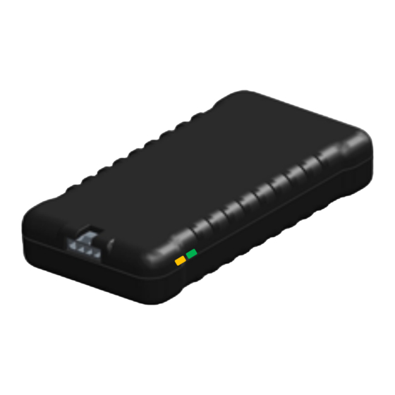
Green and White Wires
The cable provided with each MTM1000 device also has green and white wires that for most regular
installations will not be used. For starter interrupt relay installations the green wire is used connecting
the device to the relay (ref diagram below). For special applications the white wire can be used for
ignition sense.
Advertisement
Table of Contents

Summary of Contents for My True Miles MTM1000 Series
- Page 1 Quick Installation Guide MTM1000 Series MTM1000 Series Installation Steps How to Hard Wire your GPS Tracking Unit Your GPS tracking device comes with a wiring harness. All electronics and antennas are internal to the device. Tools you may use to perform the installation include: Screwdrivers, Wire strippers and cutters, Crimping tool, Voltmeter. Additional materials you might use: Connectors, Tape, Zip Ties For basic operation, connections are required to constant Power (+12V) and to Ground (sometimes called negative). It is very important to ensure that your installation will last through the use of the vehicle. The environment inside a vehicle is harsh due to vibration, temperature extremes, corrosion, humidity, and unexpected events. The primary cause of failure for vehicle tracking devices is the unexpected disconnection of the power or ground wires. Connecting Constant +12V Power (Red wire) First, use the multi-meter to find a source of CONSTANT +12V near the dashboard of the car. There are multiple places where this can be found, and the locations vary between vehicles. Some locations are more discreet than others, so plan your installation according to your needs. You may find specific wiring details for your vehicle on the internet to assist in locating the wires you need. For example, http://www.the12volt.com/ is one such source. Ensure that the wire you choose is a CONSTANT source of +12V. The multi-meter should show approximately 12V between your source and chassis ground regardless of the Ignition Switch position, and whether doors are open or closed, lights or other accessories are on or off, etc. Using your preferred connector type, or solder, connect the RED wire from the tracker to the source of +12V. Be sure not to permanently disconnect the 12V source to other circuits in the vehicle and take care to make a strong connection to survive vibration and temperatures. 2) Connecting Ground (Black wire) The black wire must be connected to a source of chassis ground. This can be either another grounded wire, or a clean metal connection to the chassis of the vehicle. Be sure not to permanently interrupt the ground connection to any other circuit in the vehicle and that you have a strong and clean connection. Green and White Wires The cable provided with each MTM1000 device also has green and white wires that for most regular installations will not be used. For starter interrupt relay installations the green wire is used connecting the device to the relay (ref diagram below). For special applications the white wire can be used for ignition sense.
- Page 2 Testing The Installation Test the installation by turning the car on and off, opening and closing the driver's door, and turning lights and dome lights on and off. Constant power should not be interrupted by these actions, and the device should continue to operate as you can tell by looking at the lights. Verify LED Status Color Function What to Look For Orange Cellular Network Blinking = Searching Solid = Cellular signal is OK Green GPS Network Blinking = Searching Solid = GPS Signal is OK Starter Interrupt (SID) Installation Optional Starter Wire 1. With a Voltmeter, find the wire from the key that activates the starter. To Key To Starter CUT 2. This link may help you identify the correct wire for different vehicles Switch http://www.bulldogsecurity.com/bdnew/vehiclewiringdiagrams.aspx 3. Cut the wire, and connect the Blue wire from the SID to the end which goes toward the key. It should show about 12V when the key is on Start, but 0V otherwise. 4. Connect the Red wire from the SID to the other cut end of the Ignition wire. 5. Connect the Green wire from the SID to the Green wire from the Tracker. To Tracker There are a number of videos and guides on the internet, but note that relays Green Wire come with many different colors of wires. You should go by the position in the relay socket, not just the color of the wire. Relay Tracker Mounting Guidelines The GPS device is intended to be inside the cabin of a vehicle, and is not waterproof. It is not designed to be mounted externally or under the hood of a vehicle. The GPS device contains internal Cellular and GPS antennas, so the location and orientation of the device is important for reliable tracking. The location should be somewhere such that no metal is between the device and the sky. A typical location...
Need help?
Do you have a question about the MTM1000 Series and is the answer not in the manual?
Questions and answers