Table of Contents
Advertisement
Quick Links
ELECTROSPINDLE
3-PHASE ASYNCHRONOUS MOTOR
MODEL: QE-1F 7.5/6 24 63F NC CB
CODE: 29L0385638C
Rev. 00 (12/18)
• ASSEMBLY INSTRUCTIONS
• USER MANUAL
(TRANSLATION OF THE ORIGINAL INSTRUCTIONS)
SCM GROUP SpA HITECO
SS 258 Marecchia, 34
47826 Villa Verucchio*RN –Italia
tel. +39 0541 674940
info@hiteco.net
www.hiteco.net***
Advertisement
Table of Contents

Summary of Contents for Hiteco QE-1F 7.5/6 24 63F NC CB
- Page 1 ELECTROSPINDLE 3-PHASE ASYNCHRONOUS MOTOR MODEL: QE-1F 7.5/6 24 63F NC CB CODE: 29L0385638C Rev. 00 (12/18) • ASSEMBLY INSTRUCTIONS • USER MANUAL (TRANSLATION OF THE ORIGINAL INSTRUCTIONS) SCM GROUP SpA HITECO SS 258 Marecchia, 34 47826 Villa Verucchio*RN –Italia tel. +39 0541 674940 info@hiteco.net...
-
Page 3: Document Information
DOCUMENT INFORMATION SCM GROUP Spa HITECO MANUFACTURER: SS 258 Marecchia 34 ADDRESS: 3-PHASE ASYNCHRONOUS MOTOR NAME HITECO BRAND QE-1F 7.5/6 24 63F NC CB MODEL: 29L0385638C CODE: • ASSEMBLY INSTRUCTIONS • USER MANUAL TYPE OF DOCUMENT: (ORIGINAL INSTRUCTIONS) 90L0505599B DOCUMENT CODE:... - Page 7 INDEX Preliminary information ....................Machine identification Intended use Risks connected to using the product Incorrect use that can be reasonably expected Specific risks with electrospindle in maintenance Aim of the manual General warnings Carrier and handling warnings Installation warnings 1.10 Warnings for the assigned personnel 1.11 Maintenance warnings 1.12 Meaning of the symbols 1.13 Description of the safety signals and their location...
- Page 8 INDEX Device for locking and toolholder expulsion Tool Tool holder unit (taper + tool + clamping parts) 2.8.1 Max. working speed according to the tool size 2.8.2 Examples of determining the max machining speed 3 - Handling, storage and unpacking ................Warnings Packaging Dimensions and weights...
- Page 9 INDEX 4.4.3 Compressed air circuit 4.4.4 Pressurisation 4.4.5 Cleaning air jet of the tool holder taper 4.4.6 Tool with air flow (option) Compressed air cooling Hydraulic cooling circuit 4.6.1 Hydraulic connections 4.6.2 Cooling fluid 4.6.3 Hydraulic circuit Electrical circuit 4.7.1 Basic connection (CB) 4.7.2 Power contacts layout 4.7.3 Signal contacts layout 4.7.4 Electrospindle wiring...
- Page 10 INDEX 4.9.4 Tool release manual command pushbutton for PLUG connection (PP) 4.10 Encoder connection 4.10.1 Encoder contacts layout 4.11 Two-voltage electrical connection (BT) Basic 4.11.1 Terminal board electrical connection Two-voltage electrical connection (BT) PP 4.12 4.12.1Terminal board electrical connection 4.13 Electrical power circuit 5 - General checks after the installation ................
- Page 11 INDEX 6.4.3 Logical management of the sensors output 6.4.4 Sensor S3 output 6.4.5 Thermal alarm and its management 6.4.5.1 Technical specifications of the thermal alarm 6.4.6 Electric fan rotation Electric fan 6.5.1 Technical specifications of the electric fan 6.5.2 Monitoring the electric fan ENCODER (optional) 6.6.1 General description 6.6.2 Sin –...
- Page 12 INDEX Unscheduled maintenance ..................Sensors replacement and adjustment 8.1.1 Access to the sensors 8.1.2 Position and description of the sensors units 8.1.3 Sensor units replacement 8.1.4 Diagrams for the adjustment of sensors units S1 and S2 (ISO) 8.1.5 Diagrams for the adjustment of sensors units S1 and S2 (HSK) 8.1.6 S1 sensor adjustment “tool clamped correctly”...
- Page 13 29L0385638C 1 - Preliminary Information INDEX Machine identification Intended use Risks connected to using the product Incorrect use that can be reasonably expected Specific risks with electrospindle in maintenance Aim of the manual General warnings Carrier and handling warnings Installation warnings 1.10 Warnings for the assigned personnel 1.11 Maintenance warnings 1.12 Meaning of the symbols...
-
Page 14: Machine Identification
The plate shown in the figure contains the machine ID data: this must be provided every time one of our assistance centres is contacted. The following information is shown: Name - ASYNCHRONOUS 3-PHASE MOTOR Brand - HITECO Model - for example: ELETM MG-2 9/6 15 I40 Code - for example: 29L0456651E Kg - WEIGHT (Kg) Main electromechanical data: frequency (Hz), voltage (V), current (A), power (kW). -
Page 15: Barcode (Example)
29L0385638C 1 - Preliminary Information BARCODE, DO NOT REMOVE. Barcode (example) 3/11 Chap. - Page THIS MANUAL CANNOT BE REPRODUCED IN WHOLE OR IN PART... -
Page 16: Intended Use
Risks connected to using the product HITECO does not know and cannot know the product installation methods, therefore the installer or the final customer must carry out a risk assessment specifically for the installation method and type. -
Page 17: Preliminary Information
29L0385638C 1 - Preliminary Information UNINTENDED USE REASONABLY EXPECTABLE - Use exclusively tool holders that comply with the standards indicated in this manual. - Check that the conical surfaces of the tool holder engage with the electrospindle, are clean and are not damaged. In fact dirt and dents can compromise the perfect coupling between the tool holder and the electrospindle spindle. -
Page 18: Aim Of The Manual
1 - Preliminary Information Specific risks with electrospindle in maintenance To operate in safety on an Hiteco product installed on a machine refer to the machine's manual. - Before proceeding with any maintenance operation make sure that the electrospindle spindle has stopped completely. -
Page 19: Preparation For Installation
They must check the perfect operation of the whole system before starting the equipment. If there are any doubts contact HITECO directly or an authorised support centre. - The systems must be executed correctly before installing the machine. -
Page 20: Meaning Of The Symbols
29L0385638C 1 - Preliminary Information 1.12 Meaning of the symbols GENERIC DANGER It indicates a procedure, activity or action that, if not carried out correctly or complied with, can cause injuries to people. SMB124 WARNING! It indicates a procedure, activity or action that, if not carried out correctly or complied with, can damage or destroy completely the product. - Page 21 System used to clamp the tool to the spindle of the electrospindle described in ISO30 standard DIN69871-1. ISO30 TAPER HITECO ROD DIN 69871-1 CODE 03L0036718D System used to clamp the tool to the spindle of the electrospindle described in standard DIN69893.
-
Page 22: Warranty Conditions
1.15.2 The warranty begins from the component registration date with Hiteco. The life of the component is calculated from the registration date to the date it returns to the Hiteco plant (with ref. ddt). After the aforementioned period the warranty will no longer be provided in any form and for any reason and without Hiteco having to provide any explanation. - Page 23 Moreover Hiteco is not responsible for damage or deterioration of any nature caused by the unintended use or use not indicated in the Use and Maintenance Manual and in any case due to an incorrect use or treatment of the Hiteco...
- Page 24 29L0385638C 2 - Technical specifications INDEX Electrospindle lay-out Mechanical specifications and electrospindle performance Inverter speed parameter setting 2.3.1 Installation Parameters Noise emission level Main parts Device for locking and toolholder expulsion Tool Tool holder unit (taper + tool + clamping parts) 2.8.1 Max.
- Page 25 29L0385638C 2 - Technical specifications Electrospindle lay-out 2/18 Chap - Page THIS MANUAL CANNOT BE REPRODUCED IN WHOLE OR IN PART...
- Page 26 29L0385638C 2 - Technical specifications Mechanical specifications and electrospindle performance Tensione / Tension 3000 6000 12000 24000 Numero giri / Nominal speed [RPM] Frequenza / Frequency [Hz] Servizio S1 / Service S1 Potenza S1 / Power S1 [kW] Coppia S1 / Torque S1 [Nm] 11.9 11.9...
- Page 27 29L0385638C 2 - Technical specifications SMB124 The motor power supply voltage must be supplied by an inverter with frequency PWM minimum of 8 kHz. Check that the actual power supply voltage is within the range ± 5% in relation to the indicated values. SMB124 The wave shape PWM of the power supply voltage must have values of dV/dt<2 kW/[u]s.
-
Page 28: Technical Specifications
29L0385638C 2 - Technical specifications Inverter speed parameter setting For this type of electrospindle the main parameters for the inverter setting are described below. 29L0385638C ELETM electrospindle. QE-1F 7.5/6 24 63F NC CB Parameters Unit of Default measurement Number of poles... - Page 29 29L0385638C 2 - Technical specifications 2.3.1 Installation Parameters 6/18 Chap - Page THIS MANUAL CANNOT BE REPRODUCED IN WHOLE OR IN PART...
-
Page 30: Noise Emission Level
Hiteco, manufacturer of the electrospindle, declares: Electrospindle model Series Noise emission level QE-1F 7.5/6 24 63F NC CB Powertech 400 73.6 dB(A) at 24000 RPM The noise emission level declared above has been measured in semi-anechoic chamber in compliance with standard ISO 3744 2010, in the operating conditions UNI EN ISO 1680:2001. -
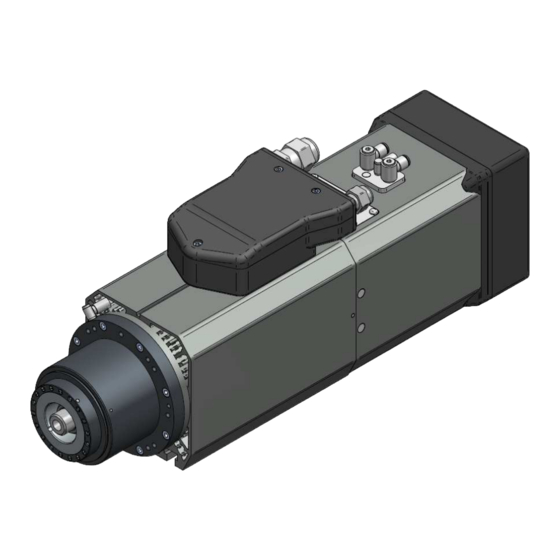
Page 31: Main Parts
29L0385638C 2 - Technical specifications Main parts Pos. Description Electrospindle HSK tool taper mounting Nose Casing “T” shaped grooves for clamping Electrical connection Manual release pushbutton Identification plate Sensors compartment Pneumatic connectors Electrofan Electrospindle serial number Aggregates clamping threaded holes Electrospindle clamping table Block/release cylinder Tab groove... - Page 32 8 kN AFTHER cleaning and lubrication of the collet the electrospindle as to be send to the service for inspection. The inspection have to be performed by a trained technician designated by Hiteco. Passed the 500000 tool change cycles the pull-in inspection have to be performed each 150000 cycles.
- Page 33 29L0385638C 2 - Technical specifications Tool (6.5 21e ce) The balancing degree of the tools must meet the requirements indicated in par.2.8 when they are fitted as a unit to the toolholder. The dynamic balancing degree of the tools must be G=1 mm/s (Norm ISO 1940) at the highest speed indicated by the manufacturer on the tool according to Norm 847-1.
- Page 34 29L0385638C 2 - Technical specifications Toolholder unit (taper + tool + fastening elements) (6.6 21e ce) - HSK toolholder taper shall comply with the Norm DIN69893. - The balancing is to be carried out with assembled toolholder unit (toolholder taper + fastening elements). - At the highest tool use speed, the dynamic balancing degree of the toolholder unit shall be G 6.3 mm/s or better (see Norm ISO 1940).
- Page 35 29L0385638C 2 - Technical specifications 2.8.1 Max. working speed according to the tool size (6.7 21e ce) Always use rotation and feed speed as well as tool diameter and length proper for the working. The operator shall select the electric spindle speed in order that it is LOWER than: - the max.
- Page 36 29L0385638C 2 - Technical specifications The values indicated in the tables are approximate: the user shall evaluate the highest speed which permits the safe working. TOOL TYPE "A": DISK CUTTER Steel cylindrical cutter, diameter tool holder d=30 mm, max. working speed [rpm] : TABELLA T1 / TABLE T1 220 D[mm] 21372...
- Page 37 29L0385638C 2 - Technical specifications TABELLA T1 / TABLE T1 350 D[mm] 9709 9227 8775 8350 7951 7576 7223 6891 6578 6282 6004 5742 5494 8400 7972 7572 7198 6848 6520 6212 5923 5651 5396 5155 4928 4715 7368 6986 6631 6299 5990...
- Page 38 29L0385638C 2 - Technical specifications Aluminium cylindrical cutter, tool holder diameter d=30 mm, max working speed [rpm]: TABELLA T2 / TABLE T2 D[mm] 25240 24514 23756 22977 22186 21391 20599 19816 19047 18294 17560 16848 16158 15492 24480 23561 22630 21700 20781 19881...
- Page 39 29L0385638C 2 - Technical specifications Cylindrical cutter made of steel+ aluminium , max. working speed [rpm] : TABELLA T3 / TABLE T3 D[mm] 22708 21610 20535 19494 18496 17545 16643 15791 14986 14228 13514 12841 12207 11610 21372 20113 18921 17802 16758 15787...
- Page 40 29L0385638C 2 - Technical specifications TOOL TYPE "B": SHANK CUTTER Max. speed according to the shank cutter dimensions TABELLA T4 / TABLE T4 D[mm] 32000 32000 32000 32000 32000 31000 31000 31000 31000 31000 30000 32000 32000 32000 32000 31000 31000 31000 31000...
- Page 41 29L0385638C 2 - Technical specifications 2.8.2 Examples to determine the max. working speed (6.7.1 21e ce) Example 1. Steel cylinfrical cutter Ø125 L100 with max. speed of 10000 rpm. With these data use table T1 "Shank cutter Ø90-210" by taking as a length the value 100 mm and as a diameter the value 130 mm to ensure safety, obtaining 8642 rpm as max.
- Page 42 29L0385638C 3 - Handling, storage and unpacking INDEX Warnings Packaging Dimensions and weights Handling Unpacking Storage Chap. - Page THIS MANUAL CANNOT BE REPRODUCED IN WHOLE OR IN PART...
-
Page 43: Dimensions And Weights
29L0385638C 3 - Handling, storage and unpacking Warnings Hoisting and handling the product are potentially hazardous operations. Follow the indications given in this manual. The installation and assembly must always be performed by specialised technicians. Packaging The machine is shipped in a cardboard package or wooden crate. Inside the packaging the product is protected with bubble wrap sheets or secured with wooden supports. - Page 44 29L0385638C 3 - Handling, storage and unpacking Handling The user is responsible for selected the most suitable lifting equipment (ropes, bands or chains, etc.) in terms of function and lifting capacity, for the mass indicated on the package and the plate.
- Page 45 29L0385638C 3 - Handling, storage and unpacking Storage If the product needs to be stored, leave it in its packing, which will protect it from the weather, damp, dust and atmospheric and environmental agents. SMB124 Manually rotate the electrospindle spindle at least once every 2 months to maintain the optimal greasing of the bearings.
- Page 46 29L0385638C 4 - Installation INDEX Preliminary checks Availability of auxiliary systems in the factory Mechanical connections 4.3.1 Electrospindle support table 4.3.2 Securing the electrospindle 4.3.3 Positioning with electric fan air cooling Compressed air connections 4.4.1 Air purity of the compressed air circuit 4.4.2 Compressed air connection points on the electrospindle 4.4.3 Compressed air circuit 4.4.4 Pressurisation...
- Page 47 29L0385638C 4 - Installation 4.7.4 Electrospindle wiring 4.7.5 Tool release manual command pushbutton for BASIC connection (CB) Circular connectors connection (CC) 4.8.1 Power contacts layout 4.8.2 Signal contacts layout 4.8.3 Electrospindle wiring 4.8.4 Tool release manual command pushbutton for circular connectors connection (CC) PLUG connection (PP) 4.9.1 Power contacts layout 4.9.2 Signal contacts layout...
-
Page 48: Preliminary Checks
29L0385638C 4 - Installation Preliminary checks Before performing any operation, CHECK that the electrospindle has not been knocked (with particular attention to the front ring nut) and that the contacts of the electrical connection have not been damaged. Availability of auxiliary systems in the factory The customer is responsible for the preparatory works (e.g. - Page 49 29L0385638C 4 - Installation 4.3.2 Securing the electrospindle The electrospindle must be secured to the support plate with M8 nuts for T-shaped slot with a tightening torque of 10 Nm. Alternatively to the nuts, wedges with the same profile can be used and supplied on request (contact the technical support service).
-
Page 50: Compressed Air Connections
29L0385638C 4 - Installation 4.3.3 Positioning with electric fan air cooling (4.3.3 45f ce) If the air cooling is performed with the electric fan, position the electrospindle so that there are at least 80 mm from the electric fan grill. This maximises the performance of the electric fan. - Page 51 29L0385638C 4 - Installation 4.4.2 Compressed air connection points on the electrospindle The compressed air connections are shown in the figure. REF. Name Function Pressure Ø Pipe RELEASE Tool release 6 – 6.5 bar Ø6x4 Tool clamp + pressurization 6 – 6.5 bar Ø4x2.5 CLAMP Tool holder cleaning blow 6 –...
-
Page 52: Compressed Air Circuit
29L0385638C 4 - Installation 4.4.3 Compressed air circuit Mains supply µ Pre-filter 5 µ Oil separator filter 0.1 Pressure regulator Monostable 5/2 solenoid valve Monostable 3V/2P solenoid valve Quick discharge valve Electrospindle Only use solenoid valves with the following specifications: - MONOSTABLE - FOR DRY AIR - MAXIMUM OPERATING PRESSURE 10 bar... - Page 53 29L0385638C 4 - Installation The solenoid valves discharges that operate the clamp/release and the taper blow must have independent discharges and NOT SHARED with other solenoid valves of the machine, otherwise there may be serious malfunctions when operating the electrospindle. This must be complied with even if the solenoid valves are part of a pack that performs other different functions.
- Page 54 29L0385638C 4 - Installation 4.4.4 Pressurisation The pressurisation is a continuous air jet that seals the mechanical seals between the front ring nut and the electrospindle nose. It comes from the electrospindle clamping air automatically. SMB124 Seeing as the hot air contained inside the electrospindle that has machined, when it cools, allows external air contaminated with dust to enter, we recommend closing the compressed air that feeds the machine 10-15 minutes after switching off the machine.
- Page 55 29L0385638C 4 - Installation 4.4.6 Tool with air flow (option) The spindles with this option can supply an air flow to the tool during machining. SMB124 The air flow requires that the tool or the tool holders have holes to allow that air to flow to the cutting edges.
- Page 56 29L0385638C 4 - Installation Two additional uni-directional valves are required, see diagram above. SMB124 To supply the tool air flow, the machine logic must comply with the following requirements: - Start the tool air flow after 300 ms from the spindle start. - Interrupt the tool air flow after 300 ms from the start of the spindle deceleration.
- Page 57 29L0385638C 4 - Installation SMB124 For tools with a transversal section of the internal holes larger than 8 mm2 (generally a tool with a tang with diameter > Ø10 mm) sealed collets must be used (see bottom left figure). These collets have internal seals to guarantee the seal with the ring nut.
- Page 58 29L0385638C 4 - Installation Compressed air cooling Certain models are cooled with compressed air. This solution reduces the length of the spindle by 44 mm compared to the version with fan. Moreover the minimum installation distance required for the fan could be avoided (see chap.
-
Page 59: Hydraulic Connections
29L0385638C 4 - Installation Hydraulic cooling circuit The hydraulic cooling circuit is found only on liquid cooled models. 4.6.1 Hydraulic connections Identify the fittings for the hydraulic connections on the electrospindle layout. 4.6.2 Cooling fluid To prevent rust from forming inside the electrospindle, that could compromise the efficiency of the hydraulic circuit, the cooling fluid must contain sufficient anti-corrosion additives. -
Page 60: Hydraulic Circuit
29L0385638C 4 - Installation 4.6.3 Hydraulic circuit The cooling circuit shown in the figure is purely indicative. Note that the dotted part represents the cooling control unit that can be: - a heat exchanger (cooling core + pump) - a chiller The cooling control unit must comply with the following specifications: Electrospindle Cooling power... -
Page 61: Electrical Circuit
29L0385638C 4 - Installation Electrical circuit 4.7.1 Basic Connection (CB) On the electrospindle there is a quick electrical connection, positioned on the electrospindle casing. On the cover of the electrical box there is a plate indicating the type of electrospindle and the main mechanical and electrical specifications (power, absorbed current, rotation current). - Page 62 29L0385638C 4 - Installation 4.7.2 Power contacts layout For the power supply of the phases inside the power wiring, use cables with a section of 6 mm2 (AWG 10) with a current density suitable for the electrospindle absorption indicated on the identification plate.
- Page 63 29L0385638C 4 - Installation SMB124 The wave shape PWM of the power supply voltage must have values of dV/dt<2 kV/micros. If not an an inductance-filter must be inserted between the inverter and the electrospindle that can flatten such voltage peaks that are harmful for the stator windings. The inductance must be sized as follows: - Impedance value: 0.045 mH on the 3 phases.
- Page 64 29L0385638C 4 - Installation 4.7.3 Signal contacts layout Meaning of the following elements: - S1 sensor – Tool clamped correctly - S2 sensor – Collet open - S3 sensor – Spindle rotation - Tool change pushbutton - Stator heat probe For further information see Chapter 6.
- Page 65 29L0385638C 4 - Installation 4.7.4 Electrospindle wiring Pos. Description Motor side shielding Power cable gland Signal cable gland Sheet metal fixing screw The wiring cables are secured to the electrospindle with cable glands 2 and 3. The power connections (cable gland 2) must be connected to the internal screw terminal board. The signal connections (cable gland 3) must be connected to the internal spring terminals.
- Page 66 29L0385638C 4 - Installation 4.7.5 Tool release manual command pushbutton for BASIC connection (CB) The position of the tool release manual command pushbutton is indicated in paragraph 2.5 "Main parts of the electrospindle". The pushbutton can be included in the consents chain to manually control the release of the tool holder.
- Page 67 29L0385638C 4 - Installation Circular connectors connection (CC) On the electrospindle there is a quick electrical connection, positioned on the electrospindle casing. On the cover of the electrical box there is a plate indicating the type of electrospindle and the main mechanical and electrical specifications (power, absorbed current, rotation current).
- Page 68 29L0385638C 4 - Installation 4.8.1 Power contacts layout DESCRIZIONE / DESCRIPTION COLORE / COLOR U1 - Fase Motore / Motor phase Marrone / Brown Giallo / Verde – Yellow / Green W1 - Fase Motore / Motor phase Nero / Black V1 - Fase Motore / Motor phase Blu / Blue N.C.
- Page 69 29L0385638C 4 - Installation SMB124 The wave shape PWM of the power supply voltage must have values of dV/dt<2 kV/micros. If not an an inductance-filter must be inserted between the inverter and the electrospindle that can flatten such voltage peaks that are harmful for the stator windings. The inductance must be sized as follows: - Impedance value: 0.045 mH on the 3 phases.
-
Page 70: Installation
29L0385638C 4 - Installation 4.8.2 Signal contacts layout CONNECT THE ELECTRIC FAN ONLY IF PRESENT (SERVO-VENTILATED AIR COOLING) N.C. = NON COLLEGATO / NOT CONNECTED Meaning of the following elements: - S1 sensor – Tool clamped correctly - S2 sensor – Collet open - S3 sensor –... - Page 71 29L0385638C 4 - Installation 4.8.3 Electrospindle wiring Pos. Description Motor side shielding Sheet metal fixing screw Power connector Signal connector The power connector is a standard M23 circular connector with 4 +4 contacts, in a metal housing. The signal connector and the encoder connector are standard M23 circular connectors with 17 contacts, with a metal housing.
- Page 72 29L0385638C 4 - Installation SMB124 In the electrospindle wiring the circular connectors that are connected to the spindle must be connected to the shielding of the respective cables SMB124 The power cable, the signal cable and encoder cable, when present, must guarantee a shielding grade of 85%.
- Page 73 29L0385638C 4 - Installation 4.8.4 Tool release manual command pushbutton for circular connectors connection (CC) The position of the tool release manual command pushbutton is indicated in paragraph 2.5 "Main parts of the electrospindle". The pushbutton can be included in the consents chain to manually control the release of the tool holder.
- Page 74 29L0385638C 4 - Installation PLUG connection (PP) On the electrospindle there is a quick electrical connection, positioned on the electrospindle casing. On the cover of the electrical box there is a plate indicating the type of electrospindle and the main mechanical and electrical specifications (power, absorbed current, rotation current).
- Page 75 29L0385638C 4 - Installation 4.9.1 Power contacts layout For the power supply of the phases inside the power wiring, use cables with a section of 6 mm2 (AWG 10) with a current density suitable for the electrospindle absorption indicated on the identification plate.
- Page 76 29L0385638C 4 - Installation SMB124 The wave shape PWM of the power supply voltage must have values of dV/dt<2 kV/micros. If not an an inductance-filter must be inserted between the inverter and the electrospindle that can flatten such voltage peaks that are harmful for the stator windings. The inductance must be sized as follows: - Impedance value: 0.045 mH on the 3 phases.
- Page 77 29L0385638C 4 - Installation 4.9.2 Signal contacts layout n. u. = not used. If the position is not used, the contact is not assembled for economical reasons. Meaning of the following elements: - S1 sensor – Tool clamped correctly - S2 sensor – Collet open - S3 sensor –...
- Page 78 29L0385638C 4 - Installation 33/45 Chap. - Page THIS MANUAL CANNOT BE REPRODUCED IN WHOLE OR IN PART...
- Page 79 29L0385638C 4 - Installation 4.9.3 Electrospindle wiring The wiring on the electrospindle is performed with a cable mounted plug available on request. Pos. Description Motor side shielding Sheet metal fixing screw Power cable gland Signal cable gland The plug has a thread to secure the metal shielding with the cable gland M25x1.5, from the cable gland a multipolar power supply cable comes out with an external sheathing of Ø9-16.5 mm (3 in figure).
- Page 80 29L0385638C 4 - Installation SMB124 In the plug wiring check that the screws are tightened to guarantee continuity between the shielding and the power and signal cables. SMB124 The power cable and the signal cable must guarantee a shielding grade of 85%. SMB124 When connecting the plug with the electrospindle, with the screws supplied, check that the shielding is secured to the casing of the electrospindle (see photo below).
- Page 81 29L0385638C 4 - Installation 4.9.4 Tool release manual command pushbutton for PLUG connections (PP) The position of the tool release manual command pushbutton is indicated in paragraph 2.5 "Main parts of the electrospindle". The pushbutton can be included in the consents chain to manually control the release of the tool holder.
- Page 82 29L0385638C 4 - Installation 4.10 Encoder connection Pos. Description M23 ENCODER connector 37/45 Chap. - Page THIS MANUAL CANNOT BE REPRODUCED IN WHOLE OR IN PART...
- Page 83 29L0385638C 4 - Installation 4.10.1 Encoder contacts layout M23 ENCODER CONNECTOR DESCRIPTION COLOUR Ua + ENCODER WHITE Ua - ENCODER BROWN Un + ENCODER GREY N.C. N.C. N.C. +0 Vcc power supply ENCODER BLUE N.C. N.C. +5 Vcc power supply ENCODER Ub + ENCODER PINK Ub - ENCODER...
-
Page 84: Installation
29L0385638C 4 - Installation 4.11 Two-voltage electrical connection (BT) Basic The electrical connection of the electrospindle is performed with a power supply and signal terminal board located in the electrical box secured on the spindle casing. On the cover of the electrical box there is a plate indicating the type of electrospindle and the mechanical and electrical specifications, such as: power, absorbed current, rotation speed, etc. - Page 85 29L0385638C 4 - Installation 40/45 Chap - Page THIS MANUAL CANNOT BE REPRODUCED IN WHOLE OR IN PART...
- Page 86 29L0385638C 4 - Installation Set the jumpers (J) in the terminal board only in the 2 positions available, see drawing (C) or (D). Different jumper (J) settings can cause injuries to people or damage to the electrospindle. (C) Position of the jumper (J) for star connection - 380 V (D) Position of the jumper (J) for triangle connection - 220 V For the power supply of the phases inside the power wiring, use cables with a section of 6 mm2 (AWG 10) with a current density suitable for the electrospindle absorption indicated on the...
- Page 87 29L0385638C 4 - Installation 4.12 Two-voltage electrical connection (BT) PP The electrical connection of the electrospindle is performed with a power supply and signal terminal board located in the electrical box secured on the spindle casing. On the cover of the electrical box there is a plate indicating the type of electrospindle and the mechanical and electrical specifications, such as: power, absorbed current, rotation speed, etc.
- Page 88 29L0385638C 4 - Installation 4.12.1 Terminal board electrical connection Connect the power supply cables to the terminal board (C) or (D) only with the electrical supply of the machine is cut off. If these indications are not complied with, there may be injuries to people and damage to the electrospindle.
- Page 89 29L0385638C 4 - Installation For the power supply of the phases inside the power wiring, use cables with a section of 6 mm2 (AWG 10) with a current density suitable for the electrospindle absorption indicated on the identification plate. The electrospindle power supply MUST be through an adequately sized and parametrised inverter, in compliance with the electrical specifications of the motor, indicated on the electrospindle plate and in point 2.2 of this manual.
- Page 90 29L0385638C 4 - Installation 4.13 Electrical power circuit TENSIONE ALIMENTAZIONE The electrospindle power supply MUST be through an adequately sized and parametrised inverter, in compliance with the electrical specifications of the motor, indicated on the electrospindle plate and in point 2.2 of this manual. 45/45 Chap.
- Page 91 29L0385638C 5 - General checks after the installation INDEX Checks before starting up 5.1.1 Positioning 5.1.2 Compressed air connections 5.1.3 Electrical connections 5.1.4 Inverter programming 5.1.5 Checks at the first start Chap. - Page THIS MANUAL CANNOT BE REPRODUCED IN WHOLE OR IN PART...
-
Page 92: Checks Before Starting Up
29L0385638C 5 - General checks after the installation Checks before starting up 5.1.1 Positioning Check that all the specifications listed in chap. 4 paragraph 4.3 have been met. 5.1.2 Compressed air connections Check that all the specifications listed in chap. 4 paragraph 4.4 have been met, and in particular: - check that the air supplying the electrospindle is DRY and that it meets the specifications listed in chap. -
Page 93: Inverter Programming
29L0385638C 5 - General checks after the installation 5.1.4 Inverter programming Check: - The maximum voltage set on the inverter must match the nominal value on the electrospindle plate. - The frequency value at which the nominal voltage value is reached must match the nominal frequency indicated on the electrospindle plate. - Page 94 29L0385638C 6 - Intended use and usage limits INDEX Environmental Conditions Running-in Pre-heating Sensors 6.4.1 Technical specifications of the inductive sensors 6.4.2 State of the electrospindle and output of the sensors S1, S2 and S5 (optional) 6.4.3 Logical management of the sensors output 6.4.4 Sensor S3 output 6.4.5 Thermal alarm and its management 6.4.5.1 Technical specifications of the thermal alarm...
-
Page 95: Environmental Conditions
29L0385638C 6 - Intended use and usage limits 6.1 Environmental Conditions The electrospindle can be used under the following conditions. Temperature: min. +5 °C; max. +40 °C Installation height: Max. 1000 m a.s.l. (at higher altitudes, consult Manufacturer) Make sure that there is good level of brightness; the minimum lighting allowed is 300 lux. The electrospindle may not be used in the open air. - Page 96 29L0385638C 6 - Intended use and usage limits Pre-heating When starting the electrospindle for the first time in the morning, perform the following pre-heating cycle, in order to optimise the pre-loads and the lubrication conditions of the bearings. The pre-heating cycle extends the life of the electrospindle. The pre-heating cycle must be performed with the tool holder inserted without tool and without performing any machining.
- Page 97 29L0385638C 6 - Intended use and usage limits 6.4.1 Technical specifications of the inductive sensors The sensors S1, S2, S3 and S5 (optional) are inductive sensors (proximity) with the following specifications: Type: PNP proximity normally open (N.O.) Supply voltage 22 ÷ 26 V DC Nominal sensitivity 0.8 mm Maximum load...
- Page 98 29L0385638C 6 - Intended use and usage limits 6.4.2 State of the electrospindle and output of the sensors S1, S2 and S5 (optional) The sensors S1 and S2 are used to manage and monitor the tool in the electrospindle, signalling to the machine when the tool has been clamped correctly or released. S5 (optional) SENSORS STATUS COLLET...
- Page 99 29L0385638C 6 - Intended use and usage limits 6.4.3 Logical management of the sensors output To define the electrospindle states of tool clamped and tool released, use the following logic diagrams based on the state of the electrospindle signals. 6/14 Chap - Page THIS MANUAL CANNOT BE REPRODUCED IN WHOLE OR IN PART...
- Page 100 29L0385638C 6 - Intended use and usage limits 6.4.4 Sensor S3 output The sensor S3 "spindle rotation" provides three "ON" impulses and two "OFF" impulses at every rotation of the electrospindle spindle as indicated in the picture. During the rotation of the electrospindle the sensor generates a set of impulses at a variable frequency according to the rotation speed.
- Page 101 29L0385638C 6 - Intended use and usage limits 6.4.5 Thermal alarm and its management The electrospindle is fitted with a "thermal alarm" consisting of a bimetallic probe sunk inside the windings of the stator, so that the control circuit is opened when th temperature exceeds values that could compromise the reliability of the electrospindle.
-
Page 102: Electric Fan
29L0385638C 6 - Intended use and usage limits Electric fan (6.9 45f ce) If the electrospindle is air cooled, it may include an electric fan to generate autonomously the cooling air flow. The electric fan is located in the rear of the electrospindle, as shown in chap. 2 paragraph 2.5 (main parts). - Page 103 29L0385638C 6 - Intended use and usage limits 6.5.2 Monitoring the electric fan The electric fan is fitted with an on-board sensor that can generate two voltage impulses for every revolution of the fan. This allows the operation of the electric fan to be monitored and prevents the electro-spindle from overheating.
-
Page 104: Encoder (Optional)
29L0385638C 6 - Intended use and usage limits ENCODER (optional) 6.6.1 General description There are four encoder models available: - Sin-Cos 128 impulses - Square wave TTL 512 impulses - Square wave TTL 1024 impulses 6.6.2 Sin – Cos encoder (optional) (6.8.6 45f ce) Specifications Values... - Page 105 29L0385638C 6 - Intended use and usage limits Cosinusoidal Wave: 1Vpp U Reference type: U (Peak A =160-240 mV) Ua+ = sinusoidal encoder signal A (2.5±0.5V) Ua- = sinusoidal encoder signal A negative (2.5±0.5V) Ub+ = cosinusoidal encoder signal B (2.5±0.5V) Ub- = cosinusoidal encoder signal B negative (2.5±0.5V) Un+ = zero signal N Un- = zero signal N negative...
-
Page 106: Specifications
29L0385638C 6 - Intended use and usage limits 6.6.3 512 square wave encoder (optional) (6.8.6 70g) The electric fan is fitted with an integrated sensor that can create 2 impulses for every revolution of the fan, if present. See paragraph 6.5.2 Specifications Values Manufacturer... - Page 107 29L0385638C 6 - Intended use and usage limits 6.6.4 1024 square wave encoder (optional) The electric fan is fitted with an integrated sensor that can create 2 impulses for every revolution of the fan, if present. See paragraph 6.5.2 Specifications Values Manufacturer Lenord+Bauer...
- Page 108 29L0385638C 7- Scheduled maintenance INDEX Checking the cleaning of the tool holder taper and of the conical seating of the spindle spindle Protection of the conical seating of the spindle spindle Cleaning and lubrication of the HSK tool holder taper Cleaning and lubrication of the HSK tool holder collet Tool pull check Compressed air circuit filters discharge...
- Page 109 29L0385638C 7- Scheduled maintenance General notes on performing any type of operation on the electrospindle, whether scheduled or unscheduled maintenance. To perform the operations safely on an electrospindle installed on the machine, refer to the manual supplied with the machine. Perform only the interventions described in this manual, following all the instructions set out scrupulously and if there are any doubts contact the technical support.
- Page 110 29L0385638C 7- Scheduled maintenance Checking the cleaning of the tool holder taper and of the conical seating of the spindle spindle Frequency: DAILY Before using the electrospindle, check that the conical seating (1) and the support plane (2) of the spindle and the corresponding coupling surfaces on the taper are clean and do not have traces of dust, grease, oil, metal particles and anything else that could compromise the ideal coupling between tool and tool holder.
- Page 111 29L0385638C 7- Scheduled maintenance cono ISO – ISO taper cono HSK – HSK taper Imperfect cleaning prevents the correct coupling of the tool holder with the spindle of the electrospindle with: - serious consequences for the SAFETY of the operator; - serious consequences on the duration of the electrospindle and the tool;...
- Page 112 29L0385638C 7- Scheduled maintenance Check that the "D" ring nut is always fitted in the tool holder taper: if it is missing dust can infiltrate inside the electrospindle. If it is missing from the tool holder, fit it. Protection of the conical seating of the spindle spindle Frequency: DAILY The seating of the tool holder body in the electrospindle spindle MUST always be protected from impurities: use an empty tool holder taper (without tool) closed with its own...
- Page 113 29L0385638C 7- Scheduled maintenance Cleaning and lubrication of the HSK tool holder taper Frequency: EVERY 2 WEEKS Every month clean thoroughly the surfaces of the tool holder with a clean and soft cloth soaked in acetone. After cleaning, lubricate with the solid, dry lubricant indicated below. TEFLUB CRC TOOL HOLDER TAPERS LUBRICATION KLUËBERT LUSIN PROTECT G31...
- Page 114 29L0385638C 7- Scheduled maintenance Cleaning and lubrication of the HSK tool holder collet Frequency: MONTHLY Every month lubricate the HSK tool holder collet of the electrospindle: use the spray grease indicated below. CHEM TREND LUSIN LUB PM 1001 HSK COLLET LUBRICATION WOLFRACOTE S5P SPRAY METAFLUX 70-81 METAL SPRAY After having stopped the electrospindle and set the machine in manual mode, move the electrospindle...
- Page 115 After 500000 tool changes the pull check must be repeated every 150000 cycles. The check must be performed by a specialised technician appointed by Hiteco. Frequency: first check after 500000 tool change cycles; the subsequent ones every 150000 tool change cycles.
- Page 116 29L0385638C 8 - Unscheduled maintenance INDEX Sensors replacement and adjustment 8.1.1 Access to the sensors 8.1.2 Position and description of the sensors units 8.1.3 Sensor units replacement 8.1.4 Diagrams for the adjustment of sensors units S1 and S2 (ISO) 8.1.5 Diagrams for the adjustment of sensors units S1 and S2 (HSK) 8.1.6 S1 sensor adjustment “tool clamped correctly”...
- Page 117 29L0385638C 8 - Unscheduled maintenance General notes on performing any type of operation on the electrospindle, whether scheduled or unscheduled maintenance. To perform the operations safely on an electrospindle installed on the machine, refer to the manual supplied with the machine. Perform only the interventions described in this manual, following all the instructions set out scrupulously and if there are any doubts contact the technical support.
- Page 118 29L0385638C 8 - Unscheduled maintenance Sensors replacement and adjustment 8.1.1 Access to the sensors The proxy sensors are located in the electrospindle under the connectors. To access the sensors, proceed as follows: Unscrew the three screws M4x30 (1), then remove the cover of the electrical box (2). B Loosen the screw M4 under the electrical box, then remove the cable glands or connectors assembly (4).
- Page 119 29L0385638C 8 - Unscheduled maintenance 8.1.2 Position and description of the sensors units Once accessed the sensors units S1, S2, S3 and S5 (optional) look as shown above. The position of the different types of sensors S1, S2, S3 and S5 (optional) is shown in the figure.. For the function of each single sensor and the relative logical operation, consult paragraph 6.4 "Sensors".
- Page 120 29L0385638C 8 - Unscheduled maintenance Each sensor is positioned inside an eccentric bush (1) and fitted with an identification band (2) and a micro connector (3) to disconnect it electrically. The eccentric bush is centres on the sensors support of the electrospindle and it is secured in position by a bracket (5) held in place by the screw (6).
- Page 121 2736240995F S5 (optional) 2736240995F Use only original sensors supplied by Hiteco. Using non-original sensors can cause serious malfunctions with a risk for the safety of people. To replace the sensor unit, follow the procedure below: A Unscrew the screw M4 (6) of the sensor to be replaced.
- Page 122 29L0385638C 8 - Unscheduled maintenance 8.1.4 Diagrams for the adjustment of sensors units S1 and S2 (ISO) For the adjustment of the sensors S1 and S2 see paragraphs 8.1.5 and 8.1.6 An incorrect adjustment of the sensors S1, S2, S3 and S5 (optional) can cause serious malfunctions such as the ejection of the rotating tool, with the risk of fatal injuries for people.
- Page 123 29L0385638C 8 - Unscheduled maintenance 8.1.5 Diagrams for the adjustment of sensors units S1 and S2 (HSK) For the adjustment of the sensors S1 and S2 see paragraphs 8.1.5 and 8.1.6 An incorrect adjustment of the sensors S1, S2, S3 and S5 (optional) can cause serious malfunctions such as the ejection of the rotating tool, with the risk of fatal injuries for people.
- Page 124 29L0385638C 8 - Unscheduled maintenance 8.1.6 S1 sensor adjustment “tool clamped correctly” Perform the following procedure: A If there is a tool, release it from the electrospindle. B Disconnect the pipe E6 (see compressed air diagram) of the electrospindle release. C Insert a pressure regulator on the disconnected pipe and connect the pressure regulator to the electrospindle with a section of pipe E6 (see compressed air diagram).
- Page 125 29L0385638C 8 - Unscheduled maintenance G With the electrospindle in release and the centesimal comparator positioned on the central nucleus of the ISO or HSK collet, gradually reduce the pressure on the release pipe with the regulator. With this reduction the central nucleus of the collet will move towards the inside of the electrospindle, pulled by the rod springs pack.
-
Page 126: Unscheduled Maintenance
29L0385638C 8 - Unscheduled maintenance FIGURE K (LIQUID COOLING) To render the adjustment easier, you can use the following circular shims that adjust the radial position of the sensor. The spare parts are as follows: SHIM FOR SENSOR UNIT ORDER CODE 0.05 mm 0336240988A 0.10 mm... - Page 127 29L0385638C 8 - Unscheduled maintenance 8.1.7 S2 sensor adjustment “collet open” Perform the following procedure: A If there is a tool, release it from the electrospindle. B Disconnect the pipe E6 (see compressed air diagram) of the electrospindle release. C Insert a pressure regulator on the disconnected pipe and connect the pressure regulator to the electrospindle with a section of pipe E6 (see compressed air diagram).
- Page 128 29L0385638C 8 - Unscheduled maintenance G Always with the electrospindle in release and the centesimal comparator positioned on the central nucleus of the ISO or HSK collet, gradually reduce the pressure on the release pipe with the regulator. With this reduction the central nucleus of the collet will move towards the inside of the electrospindle, pulled by the rod springs pack.
- Page 129 29L0385638C 8 - Unscheduled maintenance 8.1.8 S3 sensor adjustment “spindle rotation” The sensor S3 does not require any particular adjustment: simply replace the sensor, taking care to position the slot on the eccentric bush parallel to the rotation axis of the electrospindle and check that the sensor switches 3 times with every complete cycle of the spindle of the electrospindle as shown in the figure below.
- Page 130 29L0385638C 8 - Unscheduled maintenance 8.1.9 S5 sensor adjustment “piston at stroke end” (optional) Perform the following procedure: Disconnect the pipe E6 of the electrospindle tool release. Insert a pressure regulator on the disconnected pipe and connect the pressure regulator to the electrospindle with a section of pipe at the E6 tool release inlet of the electrospindle.
- Page 131 29L0385638C 8 - Unscheduled maintenance Electric fan replacement (8.1.9 45f ce) The electric fan is found only on electrospindle models with SERVO-VENTILATED AIR COOLING. Certain models of electrospindles with aspiration air cooling don't have them. Spare parts order codes for electric fan: Component Code Electric fan 127 x 127...
- Page 132 29L0385638C 8 - Unscheduled maintenance To replace the electric fan, follow the procedure below. A Unscrew the 4 screws M4 x 65 (1). B Lift the upper guard (2). C Lift the electric fan (4) disconnecting it from the power supply, by disconnecting the connector (5). D Disassemble the anti-vibration supports from the electric fan (3).
- Page 133 29L0385638C 9 - Decommissioning and scrapping INDEX Decommissioning Scrapping Chap. - Page THIS MANUAL CANNOT BE REPRODUCED IN WHOLE OR IN PART...
- Page 134 29L0385638C 9 - Decommissioning and scrapping Decommissioning Disconnect the electrospindle: - from the electrical power supply - from the compressed air supply network - from the cooling circuit (if present). Follow the installation instructions in reverse order. Clean the surfaces. Oil the parts that can be subject to oxidization, such as the HSK plane of the spindle. Cover the electrospindle end so it is properly protected against dust and dirt.
- Page 135 29L0385638C 10 - Troubleshooting INDEX 10.1 Fault – probable cause – possible solution Chap. - Page THIS MANUAL CANNOT BE REPRODUCED IN WHOLE OR IN PART...
-
Page 136: Troubleshooting
29L0385638C 10 - Troubleshooting 10.1 Fault – probable cause – possible solution BEFORE WORKING ON THE ELECTROSPINDLE, SET IN SAFETY AS INDICATED IN CHAPTER 8 "UNSCHEDULED MAINTENANCE". PROBLEM PROBABLE CAUSE SOLUTION Check the connector plug. Check the continuity and integrity of the electrical connections. - Page 137 29L0385638C 10 - Troubleshooting Remove the impurities and clean as described in Foreign bodies between chapter 7. tool holder and electrospindle spindle Clean and lubricate the collet and the taper as set Collet dirty and/or not out in chapter 7. lubricated.
- Page 138 29L0385638C 10 - Troubleshooting Check the pressure of the compressed air pipes at the top of the electrospindle, see: chap. 4 paragraph 4.4.2. Check that the outlets of the solenoid valve that drives the tool changer are not blocked see: chap. 4 paragraph 4.4.3. Check that the tubes of the compressed air circuit do not have traces of condensation and that the inlet filters are clean.
- Page 139 29L0385638C 10 - Troubleshooting The electric fan does not Check that the electric fan is working. work correctly Check that the electric fan is intact. Check that the rotation of the electric fan is not blocked by foreign bodies. Replace the electric fan if it is faulty, as indicated in chap.
- Page 140 29L0385638C 10 - Troubleshooting Incorrect inverter Check that the parameters set for the inverter Performance lower parameter settings. are coherent with the values on the electrospindle plate or indicated in chap. 2 than specifications paragraph 2.2. The tool holder is not Balance the tool holder unit as specified in chap.2 balanced paragraphs 2.7 and 2.8.
Need help?
Do you have a question about the QE-1F 7.5/6 24 63F NC CB and is the answer not in the manual?
Questions and answers