
Summary of Contents for Balflex P20
- Page 1 OPERATION MANUAL MANUFACTURING YEAR SERIAL NUMBER MANUFACTURING YEAR SERIAL NUMBER...
-
Page 2: Table Of Contents
TEST RUN SELECTING THE DIE SET P20 SELECTING THE DIE SET P32 INSTALLING THE DIE SET Quick Change Change of a single die P20, P32 SETTING THE CRIMPING DIAMETER MS CRIMPING MS CONTROL PREVENTIVE MAINTENANCE Greasing P20, P32 Oil Change Filter Change P20. -
Page 3: General
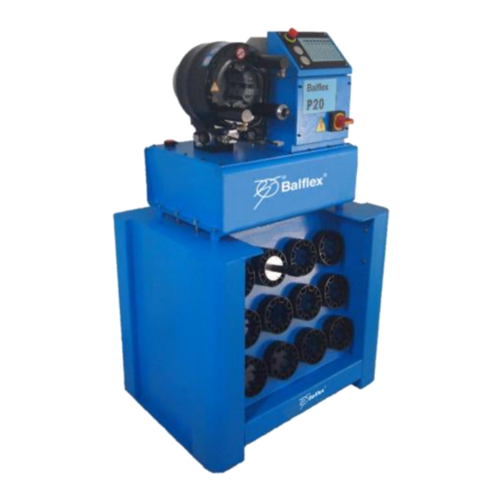
The crimping machine comprises a crimping head and a hydraulic unit mounted on the oil tank which serves as machine frame. BALFLEX crimping machine is normally delivered with a 3-phase electric motor of 4kW on P32 version, and 3kW in P20 version. On request it can be equipped with a single phase motor. -
Page 4: Mounting
The above picture shows an appropriate way to lift the machine after it has been unpacked. It is recommended to mount the machine on a BALFLEX rack. Before mounting, the rack must be screwed on the floor with four M12 wedge anchors. -
Page 5: Disposal Of The Packing Material
P20 / P32 OPERATIONS MANUAL DISPOSAL OF THE PACKING MATERIAL The transport and protective packing is mostly manufactured from the recycled or recyclable materials. Please check local environmental regulations before disposing of packing materials. Rather than throwing these materials away, please take them to your community recycling center. Handle the waste oil and filters according to law. - Page 6 P20 / P32 OPERATIONS MANUAL Warning 4 High voltage. The electric box is to be opened only by a professional electrician! Warning 5 (P32 model) The rear of the crimping head is covered by a housing protecting the operator from the crimping hazard under the housing between rear flange and cylinder.
-
Page 7: Comissioning
P20 / P32 OPERATIONS MANUAL Warning 7 When changing dies with the quick change tool, hold the handle as shown in the above figures. Make sure your hand will not get between the dies! COMMISSIONING Oil fill Fill the oil tank to center line of the indicators in the dipstick, with hydraulic oil like Shell Tellus T46 or equivalent. -
Page 8: Operation
P20 / P32 OPERATIONS MANUAL OPERATION Control identification MS -control 1. Supply disconnecting device for starting and stopping the motor. The device is used to separate the machine from power supply. However, the under voltage trip can be made dead only by disconnecting the plug or supply cable from the mains. - Page 9 P20 / P32 OPERATIONS MANUAL CRIMPING BUTTON The dies will close when this button is pressed. The dies move until the button is released or the set crimping diameter has been reached. When the machine is started with the mode selector in manual mode, crimping cannot be started using the crimping button before first selecting O-position or opening dies with retraction button 7.Dies will not open if they...
-
Page 10: Test Run
Refer to the fitting manufacturer's specifications for proper crimping diameter for the fitting. Each die set has its own crimping range. Follow it to assure the roundest possible crimping result. The minimum crimping diameter D is marked on each die set. Example: with die set Nº P20/23 the minimum crimping diameter is 23 mm. Crimping... -
Page 11: Selecting The Die Set P32
P20 / P32 OPERATIONS MANUAL SELECTING THE DIE SET P32 Use only original BALFLEX die sets in BALFLEX crimping machines. Refer to the fitting manufacturer's specifications for proper crimping diameter for the fitting. Each die set has its own crimping range. Follow it to assure the roundest possible crimping result. The minimum crimping diameter D is marked on each die set. -
Page 12: Installing The Die Set
• Die set is removed from the master dies in reverse order: close the dies, insert the tool into the die set, open the master dies and place the set back in the die table. CHANGE OF A SINGLE DIE P20, P32 • Start the motor and depress the retraction button until maximum retraction is reached. Stop the motor. -
Page 13: Setting The Crimping Diameter Ms
0.0, the resulting diameter will be the minimum diameter of the die set installed, i.e. with die set Nº P20/16 the crimping diameter will be 16 mm, Nº P20/19 gives a diameter of 19 mm etc. -
Page 14: Crimping Ms Control
EXAMPLE: Manufacturer has specified a crimping diameter of 20.6 mm for the fitting. Select die set Nº P20/19 (min crimping diameter 19 mm) according to the die chart. Turn the dial to position 1.60 (upper scale 1, lower 60). This setting will give the crimping diameter 20.6mm (19+1.6 mm).The machine has been calibrated at the factory with 40 bar pressure. -
Page 15: Preventive Maintenance
P20 / P32 OPERATIONS MANUAL • After installing the proper die set and adjusting the crimping diameter, insert the hose and fitting between the dies. • Depress and hold down the crimping push-button until the preset diameter has been reached. -
Page 16: Oil Change
P20 / P32 OPERATIONS MANUAL Oil change • Empty the tank of oil through the draining plug under the tank. • Handle the waste oil according to law. • Fill the tank to center line of the indicators in the dipstick of the filling cap. -
Page 17: Re-Calibration Of Crimping Diameter Dial
1. Re-calibrate the crimping diameter with ferrule (seamless steel tube), 0 25 mm; wall 2 mm, by using the die set Nº P20/19 or the die set P32/19 (P32). 2. Set the dial at 1.0, so that the crimping diameter will be 20 mm (see the adjacent picture) and lock the dial. -
Page 18: Troubleshooting
P20 / P32 OPERATIONS MANUAL TROUBLESHOOTING TROUBLE POSSIBLE CAUSE ACTION Machine will not start. 1. No electric supply Check fuses and supply cable connections. 2. Motor protection tripped Reset. If tripped again, check motor and pump condition. 3. Switch broken Check the voltage up to the motor. -
Page 19: Guarantee
Working and travelling costs as well as freight charges caused by guarantee repairs are not covered by the guarantee. Guarantee repairs shall be carried out at a BALFLEX distributor. In case guarantee repair is demanded, the customer has to prove that the machine is under guarantee. -
Page 20: Spare Parts List
P20 / P32 OPERATIONS MANUAL SPARE PARTS LIST Page | 19... - Page 21 PISTON ROD P-20134 P-32134 GROOVED RING P20-UN160X180 / P32-UN180X200 P-20112 P-32112 SCREW P-20135 ***** SPRING P-20145 P-32145 SCREW OF PANEL SWAGE P20-M8X60 / P32-M12X60 P-20122 P-32122 GROOVED RING P20-UN200X220X15 / P32-UN230X250X15 P-20152 P-32152 ELBOW CONNECTOR P-20136 P-32136 HYDRAULIC PIPE P-20137 P-32137...
- Page 22 P20 / P32 OPERATIONS MANUAL Page | 21...
- Page 23 P20 / P32 OPERATIONS MANUAL NAME CODE CODE ELECTRIC MOTOR P20X3KW / P32X4KW P-20201 P-32201 SCREW M14X55 P-20202 P-32202 AIR BREATHER P-20203 P-32203 COUPLING P-20301 P-32301 SCREW M6X10 P-20204 P-32204 COVER P-20205 P-32205 MAGNET PLUG PT ½” P-20401 P-32401 VALVE BLOCK...
-
Page 24: Electrical Diagram
P20 / P32 OPERATIONS MANUAL ELECTRICAL DIAGRAM Page | 23... -
Page 25: Declaration Ce
P20 / P32 OPERATIONS MANUAL DECLARATION CE OF CONFORMITY We undersigned, MANUFACTURE’S NAME BALFLEX PORTUGAL SA MANUFACTURE’S ADRESS RUA BOUÇA ESTILHADOUROS 226 – ZI ALTO VILAR – 4445-044 ALFENA - PORTUGAL Declare under sole responsibility that the following product: MACHINE TYPE...