Table of Contents
Advertisement
PULSERPLUS PRO™ HIGH RESISTANCE GROUNDING SYSTEM
INSTALLATION, OPERATION AND MAINTENANCE INSTRUCTIONS
PulserPlus Pro™ Operator Interface
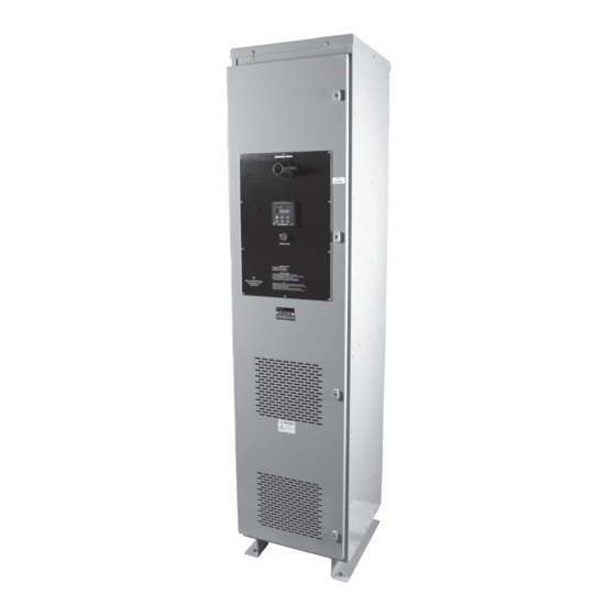
PulserPlus Pro™ NEMA 1
Freestanding Unit
4750 Olympic Blvd. • Erlanger, KY 41018 • USA
Phone: 800-537-6144 / 859-283-0778 • Fax: 859-283-2978
www.postglover.com
Serving the Electrical Industry Since 1892
© 2006 Post Glover Resistors, Inc.
PGR Document #HG111-06
Advertisement
Table of Contents

Related Manuals for Post Glover PULSERPLUS PRO

Summary of Contents for Post Glover PULSERPLUS PRO
- Page 1 PULSERPLUS PRO™ HIGH RESISTANCE GROUNDING SYSTEM INSTALLATION, OPERATION AND MAINTENANCE INSTRUCTIONS PulserPlus Pro™ Operator Interface PulserPlus Pro™ NEMA 1 Freestanding Unit 4750 Olympic Blvd. • Erlanger, KY 41018 • USA Phone: 800-537-6144 / 859-283-0778 • Fax: 859-283-2978 www.postglover.com Serving the Electrical Industry Since 1892 ©...
-
Page 2: Table Of Contents
PULSERPLUS PRO™ HIGH RESISTANCE GROUNDING SYSTEM PULSERPLUS PRO™ HIGH RESISTANCE GROUNDING SYSTEM INSTALLATION, OPERATION AND MAINTENANCE INSTRUCTIONS INSTALLATION, OPERATION AND MAINTENANCE INSTRUCTIONS Table of Contents Section Equipment Overview ................... 3 Section Operational Description ..................4 Normal Operation ....................4 Loss of Ground ....................4 Ground Fault ....................... -
Page 3: Equipment Overview
Arc Flash/Blast Reduction: Eliminates hazardous energy during ground faults, which are present in 90% of all electrical faults. This instruction booklet is intended as a general guidance tool for personnel installing Post Glover High Resistance Grounding Systems. However, each unit is designed for a specific application/installation. The detailed drawings provided with each unit supersede the general information provided in this booklet. -
Page 4: Operational Description
Harmonic alarming. 2.2 Loss of Ground When the current mentioned above goes to zero, typically this indicates a Loss of Ground condition (i.e. grounding wire failure). If this occurs, the system will be Ungrounded. The PulserPlus Pro™ controller has an Under-Current / Under-Voltage feature that detects this condition for both Fundamental and 3 Harmonics. Upon detection, the green NORMAL indicating light will turn off and its auxiliary form-C contacts change state. -
Page 5: High 3 Rd Harmonics
Harmonics High 3 harmonics are also sensed by the PulserPlus Pro™ controller. An upper limit is set by the user for detection of current or voltage across the resistor. After a time delay expires; the amber THIRD HARMONIC indicator light will illuminate, the NORMAL indicator light will turn off, and an alarm horn will sound. Upon detection, the SYSTEM NORMAL and THIRD HARMONIC auxiliary form-C contacts change state. -
Page 6: Summary Of Events
PULSERPLUS PRO™ HIGH RESISTANCE GROUNDING SYSTEM PULSERPLUS PRO™ HIGH RESISTANCE GROUNDING SYSTEM INSTALLATION, OPERATION AND MAINTENANCE INSTRUCTIONS INSTALLATION, OPERATION AND MAINTENANCE INSTRUCTIONS 4750 Olympic Blvd. • Erlanger, KY 41018 • USA Phone: 800-537-6144 / 859-283-0778 • Fax: 859-283-2978 www.postglover.com Serving the Electrical Industry Since 1892 ©... -
Page 7: Installation
PULSERPLUS PRO™ HIGH RESISTANCE GROUNDING SYSTEM PULSERPLUS PRO™ HIGH RESISTANCE GROUNDING SYSTEM INSTALLATION, OPERATION AND MAINTENANCE INSTRUCTIONS INSTALLATION, OPERATION AND MAINTENANCE INSTRUCTIONS Section 3 – Installation Post Glover High Resistance Grounding Systems are packaged in a variety of different configurations depending on the ratings and site requirements. The typical low-voltage and medium-voltage enclosures are shown in Section 9. Consult all specific equipment drawings furnished by Post Glover Resistors, Inc., for your particular... -
Page 8: Line And Control Connections
PULSERPLUS PRO™ HIGH RESISTANCE GROUNDING SYSTEM PULSERPLUS PRO™ HIGH RESISTANCE GROUNDING SYSTEM INSTALLATION, OPERATION AND MAINTENANCE INSTRUCTIONS INSTALLATION, OPERATION AND MAINTENANCE INSTRUCTIONS 3.6 Line and Control Connections Refer to application specific drawings that accompany the Post Glover system. Generally, the line connections are made from either the top or bottom of the enclosure. Space is provided for line cables to run down the side without any cable bends. -
Page 9: Start-Up Procedure
PulserPlus Pro™ module. The readings on the PulserPlus Pro™ module will be lower than normal readings due to the test resistor connected in series with the neutral grounding resistor. The purpose of the test resistor is to avoid a phase- ground-phase fault if an actual ground fault were to occur during testing. - Page 10 Press the RESET pushbutton and the red and green lights and auxiliary contacts should revert to their normal states. Without Test Resistor This test will verify operation of the PulserPlus Pro™ module only. The test bypasses the neutral grounding resistor and most of the circuitry by opening the neutral grounding circuit and applying control voltage (~120Vac) to the PulserPlus Pro™ controller module.
-
Page 11: System Capacitive-Charging Current
The magnitude of zero-sequence charging current is determined by the line-to-ground capacitance associated with system components. The value of the current must be known to properly coordinate the Post Glover High- Resistance Grounding System. In an industrial power system where the design and components are known, the charging current can be estimated with reasonable accuracy. - Page 12 PULSERPLUS PRO™ HIGH RESISTANCE GROUNDING SYSTEM PULSERPLUS PRO™ HIGH RESISTANCE GROUNDING SYSTEM INSTALLATION, OPERATION AND MAINTENANCE INSTRUCTIONS INSTALLATION, OPERATION AND MAINTENANCE INSTRUCTIONS 4750 Olympic Blvd. • Erlanger, KY 41018 • USA Phone: 800-537-6144 / 859-283-0778 • Fax: 859-283-2978 www.postglover.com Serving the Electrical Industry Since 1892 ©...
-
Page 13: Test Results
NOTE: The temporary disconnect switch and current limiting fuse associated with the phase to be grounded are not included with the PulserPlus Pro™. A portable ammeter can be included as an option with the PulserPlus Pro™. 4750 Olympic Blvd. • Erlanger, KY 41018 • USA 4750 Olympic Blvd. -
Page 14: Controller Setup
The unit may be programmed to display any or all of these measurements. 6.2 Adjustable Parameters The following features of the PulserPlus Pro™ can be set from the front panel. Fundamental Voltage Measurement On/Off... -
Page 15: Configuration Mode
PULSERPLUS PRO™ HIGH RESISTANCE GROUNDING SYSTEM PULSERPLUS PRO™ HIGH RESISTANCE GROUNDING SYSTEM INSTALLATION, OPERATION AND MAINTENANCE INSTRUCTIONS INSTALLATION, OPERATION AND MAINTENANCE INSTRUCTIONS 6.3 Configuration Mode To Enter Configuration Mode Press BOTH the RESET and DOWN ARROW buttons until the unit BEEPS, then release. -
Page 16: Hi Limit Setpoints
This feature multiplies the measured current by the selected CT ratio. For example, the physical limitation of the PulserPlus Pro™ module is 16A. If 20A is desired, a 30:5 CT is used to send a 0-5A signal the module. The CT ratio is set for 6x, so the measured current (0 to 5A) is multiplied by 6x. The display and alarming uses this... -
Page 17: Pulsing Timer
PULSERPLUS PRO™ HIGH RESISTANCE GROUNDING SYSTEM PULSERPLUS PRO™ HIGH RESISTANCE GROUNDING SYSTEM INSTALLATION, OPERATION AND MAINTENANCE INSTRUCTIONS INSTALLATION, OPERATION AND MAINTENANCE INSTRUCTIONS The Lo Limit setpoint indicates the level at which the Loss of Ground condition will activate. For a Harmonic Lo Limit, it may also indicate a Ground Fault. -
Page 18: Locate A Ground Fault
PULSERPLUS PRO™ HIGH RESISTANCE GROUNDING SYSTEM PULSERPLUS PRO™ HIGH RESISTANCE GROUNDING SYSTEM INSTALLATION, OPERATION AND MAINTENANCE INSTRUCTIONS INSTALLATION, OPERATION AND MAINTENANCE INSTRUCTIONS Section 7 – Locate a Ground Fault To locate a ground fault, activate the pulsing circuit by pressing and holding the PULSE pushbutton on the operator’s panel. -
Page 19: Maintenance
INSTALLATION, OPERATION AND MAINTENANCE INSTRUCTIONS Section 8 – Maintenance Normally, no maintenance is necessary for the PulserPlus Pro™ high resistance grounding system. However, periodic inspections are needed to ensure that the controller is functioning correctly and the resistor is still capable of protecting the system. -
Page 20: Schematics & Dimension Drawings
PULSERPLUS PRO™ HIGH RESISTANCE GROUNDING SYSTEM PULSERPLUS PRO™ HIGH RESISTANCE GROUNDING SYSTEM INSTALLATION, OPERATION AND MAINTENANCE INSTRUCTIONS INSTALLATION, OPERATION AND MAINTENANCE INSTRUCTIONS Section 9 – Schematics Figure 3 600 Volt Maximum, Wye Connected System Figure 4 600 Volt Maximum, Delta Connected System 4750 Olympic Blvd. - Page 21 PULSERPLUS PRO™ HIGH RESISTANCE GROUNDING SYSTEM PULSERPLUS PRO™ HIGH RESISTANCE GROUNDING SYSTEM INSTALLATION, OPERATION AND MAINTENANCE INSTRUCTIONS INSTALLATION, OPERATION AND MAINTENANCE INSTRUCTIONS Figure 5 Medium Voltage, Wye Connected System Figure 6 Medium Voltage, Delta Connected System 4750 Olympic Blvd. • Erlanger, KY 41018 • USA 4750 Olympic Blvd.
- Page 22 PULSERPLUS PRO™ HIGH RESISTANCE GROUNDING SYSTEM PULSERPLUS PRO™ HIGH RESISTANCE GROUNDING SYSTEM INSTALLATION, OPERATION AND MAINTENANCE INSTRUCTIONS INSTALLATION, OPERATION AND MAINTENANCE INSTRUCTIONS Section 9 – Drawings 4750 Olympic Blvd. • Erlanger, KY 41018 • USA Phone: 800-537-6144 / 859-283-0778 • Fax: 859-283-2978 www.postglover.com...
- Page 23 PULSERPLUS PRO™ HIGH RESISTANCE GROUNDING SYSTEM PULSERPLUS PRO™ HIGH RESISTANCE GROUNDING SYSTEM INSTALLATION, OPERATION AND MAINTENANCE INSTRUCTIONS INSTALLATION, OPERATION AND MAINTENANCE INSTRUCTIONS 4750 Olympic Blvd. • Erlanger, KY 41018 • USA 4750 Olympic Blvd. • Erlanger, KY 41018 • USA Phone: 800-537-6144 / 859-283-0778 •...
- Page 24 PULSERPLUS PRO™ HIGH RESISTANCE GROUNDING SYSTEM INSTALLATION, OPERATION AND MAINTENANCE INSTRUCTIONS 4750 Olympic Blvd. • Erlanger, KY 41018 • USA Phone: 800-537-6144 / 859-283-0778 • Fax: 859-283-2978 www.postglover.com Serving the Electrical Industry Since 1892 © 2006 Post Glover Resistors, Inc.
Need help?
Do you have a question about the PULSERPLUS PRO and is the answer not in the manual?
Questions and answers