Table of Contents

Summary of Contents for renray Healthcare Elite Bed Series
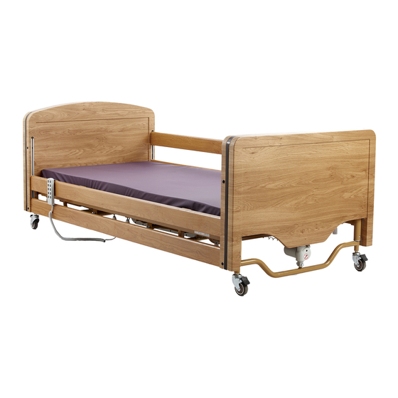
- Page 1 Elite Bed Range Models: E2000 - Elite Bed E2000L - Elite Long Bed E2060 - Elite Low Bed E2060L - Elite Low Long Bed E2400 - Elite Extra Wide Bed Instructions For Use IMPORTANT! Read the instructions in this booklet thoroughly before use...
-
Page 2: Table Of Contents
Spare Parts List ___________________________________________________________ 49 11.1.4 Disposal of Electrical Equipment __________________________________________ 49 11.2 Warranty _____________________________________________________________________ 49 11.3 Contact Renray Healthcare ___________________________________________________ 50 12 Appendix ________________________________________________________________ 51 12.1 Detailed Technical Description ________________________________________________ 51 12.1.1 Guidance & Manufacturer’s Declaration – Electromagnetic Immunity ______ 51... -
Page 3: Introduction
1 Introduction 1.1 Foreword Thank you for purchasing a Renray Elite Bed. In doing so, you have chosen a quality Bed from a range which has been designed to provide excellent functionality in a safe manner. To ensure the Elite Bed is always operated correctly and safely please read this document thoroughly and strictly follow all the assembly, operating, cleaning and... -
Page 4: Warning Symbols
1.2 Warning Symbols WARNINGS given in this manual identify possible hazards in procedures or conditions, which if not correctly followed, could result in death, injury or other serious adverse reactions. Cautions given in this manual identify possible hazards in procedures or conditions, which if not followed, could result in equipment damage or failure, and indicate moderate risk. -
Page 5: Intended Use
Intended Use Each Bed in the Renray Elite Range is intended to assist members of staff in Residential, Care and Nursing Homes to assist persons over the age of 12 years and of a height in between 146cm - 185cm (4’9½” – 6’1”) who have disabilities or need care to compensate for an injury, handicap or disability. -
Page 6: General Description
3 General Description The Elite Bed Range has been primarily designed as an electrically operated bed to assist the Carer position the Patient and also to allow the Patient to adjust their own position to aid their comfort. The Bed is constructed from welded steel fabrications coated in protective epoxy powder paint. -
Page 7: Installation
4 Installation Before you begin, you will need the following tools to assemble and disassemble the bed; 1x Phillips Screwdriver 1x Pair of Scissors 4.1 Unpacking Carefully open the boxes and unpack all components, laying all large components flat. Remove the cable ties securing the handset, cables and metal frames together. - Page 8 Part Description/Name Qty. Head Deck Assembly* Head End Assembly* Foot Deck Assembly* Foot End Assembly* Deck Joining Bar Hand wheel Mattress Retainer Bracket** Control Unit Handset Handset Lock-Out Key Side Rail* Side Rail End Caps (& Springs) Side Rail Glides Side Rail Lock Key*** Table 1 –...
- Page 9 Side Rails (x4) Head Deck* Foot End* Foot Deck* Head End* Deck Joining Bars (x2) Hand Mattress Retainer Wheels* (x8) Handset & Brackets (x4)*** Lock-Out Key Side Rail Glides (x4) Side Rail End Caps (x8) Control Unit (fitted with springs) Side Rail Lock Key** Figure 2 –...
-
Page 10: Assembly Procedure
4.3 Assembly Procedure Once all unpacking steps have been followed, you should have all the parts in Figure 2 – Part Identification. If you do not have the Transport Brackets, skip to Step 4 NOTE ► The largest bed sections may still be assembled on the Transport Brackets. - Page 11 Deck Frame Assembly If you have not done so already, clear the area you will be assembling the bed in. Ensure there is an accessible power socket close by. Plan where the Head End of the Bed will be positioned. Lay out the Deck parts, Mattress-side down.
- Page 12 Attach power cord to the Control Unit Plug the power cable into the socket on the reverse of the Control Unit as shown. Secure it in place with the cover and 2x screws (supplied) (This step can be skipped if the control box comes fitted with a power cable) Remove the covers from the control unit Locate the Control Unit, and identify the 2...
- Page 13 Stand the Mattress Deck on its side, using the head and knee sections to stabilise it. These will fold out manually, without power. Flip the Bed Deck onto its side and slide the 2 red tabs back into place to lock the Control Unit onto the Bed.
- Page 14 Connect the Control Unit Remove screws Remove screws a. Firstly, remove the screws holding the cable retaining cover in place and remove it. b. Connect the Head End Foot End actuator cables to their corresponding sockets on the Control Box. 2) Foot End 4) Head End Ensure that the...
- Page 15 Ensure that all cables are routed safely under the bed; The Head and Foot End actuator cables should be routed as in the illustration below, only going above the two bars highlighted The Mains Cable and Handset Cable must not pass through any parts of the Bed Deck.
- Page 16 Tighten the thumbscrews to secure the Bracket in place until finger-tight. Do not force them, as the brackets may deform. NOTE ► design mattress retainer brackets may differ from illustration, but they should always be fitted with the bent wire component tilting away from the bed. Repeat this process with each of the four brackets.
-
Page 17: Care, Cleaning And Disinfection
5 Care, Cleaning and Disinfection Always clean the bed before use, in particular when assigning new patients to reduce the risk of any possible cross infection. Before beginning any cleaning or disinfecting procedure, make sure you are wearing suitably protective clothing and gloves to prevent against skin irritation or other adverse skin reactions. -
Page 18: Disinfecting
Do not disconnect any cables between actuators, Handsets or the Control Box; doing so could allow fluid ingress into electrical systems. Never use any type of water or steam high pressure cleaner, jet or spray on any of the electrical components, use detergent/disinfectant on a damp cloth only. -
Page 19: Operating Instructions
6 Operating Instructions 6.1 General Safety Instructions In order to avoid risk of crushing, always ensure there are no objects or people’s limbs in any plane of movement of the Elite Bed before operating or adjusting any Bed functions. If the mental state, behaviour or other patient condition requires the restricted use of Bed functionality, the Handset can be locked using the Handset Lock-Out Key. - Page 20 Never use the Bed in the presence of explosive or flammable gasses, such as may be present in anaesthetic agents. NEVER attempt to use an Elite Bed to transport Patients. Always ensure that the underneath of the Bed is kept clear at all times. Ensure the operation and movement of the Bed is never impeded by any obstacles such as bedside furniture, electrical sockets, skirting boards or other fixtures &...
-
Page 21: Operator Safety Information
When routing cables/tubes/etc. through the Bed, always take precautions against passing them between parts of the bed that could trap, damage or shear them. NEVER route cables on the floor between the castors at the Head or Foot Ends of the Elite Bed. -
Page 22: Handset Functionality
6.4 Handset Functionality The Elite Bed is supplied with an easy to operate handset to control all the powered functionality of the Bed. It is easy to use for both the Carer and the occupant of the Bed. If circumstances require it, the Handset can be “Locked Out” to render it inoperable to anybody without a Handset Lock-Out Key. -
Page 23: Locking The Handset
Figure 3 – Handset Buttons The Function LED is lit when a button is depressed and the bed is operating. The ‘Bed Tilt’ function can place Patients in dangerous positions. This function should only be operated after reading 6.6 Bed Tilt Feature, (Page 22) thoroughly. -
Page 24: Manual Leg Section
For some medical conditions, laying a patient in the head down - feet up tilted position can be extremely dangerous to a patient! This feature should only ever be used by qualified personnel and after the Patient has been Clinically Risk Assessed. Raise Head End Raise Foot End This button will raise the... -
Page 25: Castors
Stand behind the Foot End of the Bed and grip the long mattress support with both hands. Lift it carefully until the desired position is achieved, then gently lower until it locks into place. To lower the Calf Section; The Calf Section must be fully raised before it can be lowered. -
Page 26: Bed Extension
“Mattress Squab” accessory or a correctly sized mattress. See 7.2 Mattress, Page 30 If Side Rails are required, ALWAYS ensure you have the correct length side rails fitted. If ever in doubt, contact Renray Healthcare for guidance. Page 25 of 56... - Page 27 Instructions Firstly remove the Mattress. Loosen one Hand wheel securing the Foot End to the Foot Deck, and remove one Hand wheel Pull the Foot End away from the Foot Deck, until the Extended Locator Tab lines up with the hole you removed the Hand wheel from. Replace the Hand wheel, and pull/push the Foot End to ensure the Hand wheel is in the notch before tightening fully.
- Page 28 The short Mattress for your particular model AND a compatible Mattress Squab fitted at the head end of the Bed (as illustrated). A single Mattress of the correct length. Contact Renray Healthcare for mattress types & sizes. Page 27 of 56 E200R IFU 2...
-
Page 29: Emergency Lowering Facility
6.10 Emergency Lowering Facility The Renray Elite Beds come with a facility to provide limited functionality of the bed in an emergency situation. In the event of a power failure (or disconnection from the main electricity supply) the Bed can perform a single emergency operation, for example returning the Mattress Platform to a flat position, or lowering the Bed Deck. -
Page 30: Accessories
4 x Extra Extended Side Rails, 8x End Caps & 4x Set of 4 Glides Side Rail Height Extensions Lifting Pole Side Rail Bumper Pads Fall Mat Contact Renray Healthcare or your local Mattress & Mattress Squabs representative for recommended available products Page 29 of 56 E200R IFU 2... -
Page 31: Mattress
7.2 Mattress When fitting the Mattress, always ensure it fits snugly inside of all the Mattress Retainer Brackets. This will prevent the Mattress from moving when the Bed is operated. The standard foam Mattress may not be suitable for all Patients’ conditions. This must be determined by a qualified person Clinically Risk Assessing each Patient before use. -
Page 32: Lifting Pole
If the Bed is being used in its Extended Length configuration, always fit either only the Extended Mattress, or the Standard Mattress and Mattress Squab, which will extend the Standard Mattress to full length of the extended Bed. (See 6.9 Bed Extension, Page 25) 7.3 Lifting Pole The Lifting Pole is intended to assist or support a Patient to change position by providing... -
Page 33: Side Rails
Do not use Lifting Pole for anything other than assisting patients change position in the Bed. Regularly check the condition of the Lifting Pole. If the Lifting Pole becomes loose or distorted, or the handle or straps show any signs of loose stitching, fraying, misuse or damage, replace the affected component(s) immediately or take out of service. - Page 34 Part Identification Side Rail End Cap Side Rail (containing spring) Glide Side Rail Installation First, ensure it is safe to raise the bed to its maximum height, and then do so. Locate all the 4x Side Rail Glides, and raise the bed NOTE ►...
- Page 35 Fit the Side Rail End Caps to the Side Rails, and then slide two Side Rails onto the Bottom and Top Side Rail guides, leaving their free end resting on the floor. Insert another Side Rail Glide into the free end of the side rails as shown.
- Page 36 To remove the Side Rails; Ensure it is safe to raise the Bed, and then raise it to its highest position. Hold & lift the bottom rail and press in the bottom Side Rail button to remove each glide. Make sure the Rails are in their lowest position and proceed through steps 1 to 5 in reverse.
- Page 37 If using ANY replacement mattress or mattress overlay with any Side Rails, the correct Side Rail Height Extensions MUST be fitted. (see 7.4.3 Side Rail Height Extensions, Page 38) NEVER attempt to force a Side Rail Glide to fit a Bed or a Side Rail – they should all easily fit together.
-
Page 38: Side Rail Locks
7.4.1 Side Rail Locks The Renray Elite Beds come with the option of Side Rail Locks. The Locks provide a safe, quick, neat and reliable means of restricting unauthorised personnel raising the Side Rails. When the locks are engaged, the Side Side Rail Lock Rails cannot be raised, and (if no side rails are fitted) Side Rails cannot be fitted. -
Page 39: Extended & Extra Extended Side Rails
Side Rails is required, there are separate Extended Side Rails available, and Extra Extended side rails for the E2000L and E2060L, as an accessory from Renray Healthcare. These are fitted, removed and used in exactly the same method as the standard Side Rails. -
Page 40: Fall Mat
The Fall Mat accessory is to provide some protection to Patients if they roll out when Side Rails are not fitted to the Bed. For further information on this accessory, please contact Renray Healthcare (see 11.3 Contact Renray Healthcare, Page 50) When using the Fall Mat, always leave the Bed at its lowest height. -
Page 41: Storage And Transport
8 Storage and Transport When the Bed needs to be moved or packed away for storage, it can be assembled onto the optional Transport Brackets to take up minimal floor space and allow easy manoeuvring using the Bed’s castors. 8.1 Assembling onto Transport Brackets In order to assemble the Renray Elite Bed onto the brackets, it is important it is assembled according to these instructions. - Page 42 Firstly, ensure the Head and Foot Ends are both fully lowered, and the brakes are applied to the castors. Disassemble the Bed in the exact reverse order of assembly (see 4.3 Assembly Procedure, Page 9) Use the Transport Brackets and 4 hand wheels to secure the Head and Foot Ends together exactly as shown.
- Page 43 Insert the Head Deck Head Deck Locate the Head Deck onto the remaining two uprights (closest to the Head End), so that the two decks have their mattress sides facing each other, and the ends of the decks that join each other both are both at the top.
-
Page 44: Storage & Transport Conditions
8.2 Storage & Transport Conditions When storing the Bed, following the guidance below will help to ensure the working life of the Bed. Ensure the Renray Elite Bed is stored & transported; Assembled onto the Transport Brackets (only components that can be ... -
Page 45: Troubleshooting
9 Troubleshooting POSSIBLE CAUSES FAULT SOLUTION Handset functionality has been Locate Handset Lock-Out Locked-Out Key and unlock Check mains cable is plugged fully into wall socket Check socket is turned on & working Check mains cable is properly connected to Bed Not connected to mains supply Control Unit Bed does not... -
Page 46: Technical Data
10 Technical Data 10.1 Safe Working Conditions Maximum Safe Working Maximum Load Patient (This includes Weight the weight of mattress and all fitted accessories) E2000L E2060L Elite Bed Model E2000 E2400 E2060 Mattress Size Width 1100 Depth Length Without Extension 1850 1850 1850... -
Page 47: Component Weights
10.3 Component Weights Elite Bed Model E2000 E2400 E2060 E2000L E2060L Foot End (Kg) 32.2 42.7 32.2 32.2 32.2 Head End (Kg) 35.2 45.7 35.2 35.2 35.2 Head Deck (Kg) 18.8 23.4 18.8 18.8 18.8 Foot Deck (Kg) 18.8 24.1 18.8 19.5 19.5... -
Page 48: Electrical System Data
10.4 Electrical System Data Supply Voltage 230/240V AC, 50/60Hz System Operating Voltage 24V DC Fuse (internal) 1.6 Amp Fuse (plug) 5 Amp Duty Rating Intermittent ~ (2 mins/18mins) Emergency Battery Two (2x) 9V ‘6LR61’ Alkaline Batteries Control Unit Electrical Protection Class II Type B For Indoor Use Only... -
Page 49: Maintenance & Warranty
Any faults, defects, damage or excessive wear must be dealt with immediately or the Bed should be taken out of service A full service of the Bed should be performed by Renray Healthcare or by suitably qualified and trained personnel;... -
Page 50: Servicing
Mattress Retainer Bracket 510012 Side Rail Lock Key 11.1.4 Disposal of Electrical Equipment Contact Renray Healthcare for advice on disposal of all electrical equipment on the Bed. DO NOT dispose of the Emergency Lowering 9v batteries with domestic waste or in fire. -
Page 51: Contact Renray Healthcare
11.3 Contact Renray Healthcare Web: www.renrayhealthcare.com Email: info@renrayhealthcare.com Tel: 0044 1606 593456 Fax: 0044 1606 861354 Address: Renray Healthcare, Road Five, Winsford Industrial Estate, Winsford, Cheshire, CW7 3RB January 2015 Page 50 of 56... -
Page 52: Appendix
12 Appendix 12.1 Detailed Technical Description 12.1.1 Guidance & Manufacturer’s Declaration – Electromagnetic Immunity Guidance & Manufacturer’s Declaration – Electromagnetic Immunity (Table 1 of 4) The Renray E2000 Electric Bed is intended for use in the electromagnetic environment specified below. The customer or the user of the Renray E2000 Electric Bed should assure that it is used in such an environment. - Page 53 Guidance & Manufacturer’s Declaration – Electromagnetic Immunity (Table 2 of 4) The Renray E2000 Electric Bed is intended for use in the electromagnetic environment specified below. The customer or the user of the Renray E2000 Electric Bed should assure that it is used in such an environment.
- Page 54 Guidance & Manufacturer’s Declaration – Electromagnetic Immunity (Table 3 of 4) The Renray E2000 Electric Bed is intended for use in the electromagnetic environment specified below. The customer or the user of the Renray E2000 Electric Bed should assure that it is used in such an environment.
- Page 55 Recommended separation distances between portable and mobile RF communications equipment and the Renray E2000 Electric Bed (Table 4 of 4) The Renray E2000 Electric Bed is intended for use in an electromagnetic environment in which radiated RF disturbances are controlled. The customer or the user of the Renray E2000 Electric Bed can help prevent electromagnetic interference by maintaining a minimum distance between portable and mobile RF communications equipment (transmitters) and the Renray E2000 Electric Bed as recommended below, according to the maximum output power of the communications equipment.
- Page 56 NOTES Page 55 of 56 E200R IFU 2...
- Page 57 NOTES January 2015 Page 56 of 56...
- Page 58 Web: www.renrayhealthcare.com Email: info@renrayhealthcare.com Tel: 0044 1606 593456 Fax: 0044 1606 861354 Address: Renray Healthcare, Road Five, Winsford Industrial Estate, Winsford, Cheshire, CW7 3RB...
Need help?
Do you have a question about the Elite Bed Series and is the answer not in the manual?
Questions and answers