Advertisement
Quick Links
Advertisement

Summary of Contents for DressWall Freestanding Free 1-side
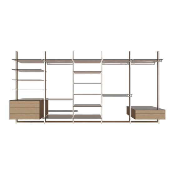
- Page 1 DressWall - Freestanding Installation manual Free 1-side Free 1-side + glass Free satellite...
- Page 2 PROFILE set AWPADK set 36,5 mm x1/set AWPADK 86,5 mm x2/set ISO14579-M5X25 x2/set x2/set MAXXFAST CK 6X50 x1/set x2/set HILTIPLUG HUD-1 8X40 x2/set HRD set 35 mm HRD-C 8X120 x5/set x1/set SHELF set 46 mm 79 mm DAW-DWLPDL DAW-DWLPDR x1/set x1/set ISO10642-M5X8 x2/set...
- Page 3 DAW-KHRDOP x2/set DAW-KHRH x2/set DressWall plinth 80 mm PAP-RGPU x1/set DAW-U80X50 x1/set (= led cover) 20 mm DressWall LED set LED-FLEX 120/M (4100K xL) (1000|9670) x2/set LED-FLEX 120/M (4100K xL) (1000|9670) x2/set 10 cm TRANSFO MD70-110/230V x1/set plug white 110/230V...
- Page 4 Remote set 500W Remote controller x1/set 6 way plug 20 cm driver 500W o on 110/240V x1/set Power cord + euro plug - 3 m x1/set 6 way plug Transfo extension cord - 2 m x1/set Extension cord 110/240V - 2 m x1/set Drawer M set (350/400/450/500/550 mm) DW-LGDLL...
- Page 5 Step 1: Check measurements See “Dresswall Freestanding - Calculate DWP profile length & module width” for more information about the applied dimensions. 4166 mm = W 791 mm DWP profile = 35 mm = module width 2083 mm 2083 mm...
- Page 6 Step 2: Define starting side Decide if you’ll install the DWP profiles from left to right or from right to left. In this example we will start from right to left, as the shortest DWP profile height is at the right side of the dressing area. 4166 mm = W laserline...
- Page 7 Step 3: DWP Profile length OPTION A - all DWP profiles ordered to ‘precut’ length All DWP profiles were ordered to 2492 mm ‘precut’ identical length in our example. If you also ordered ‘precut’ identical length , go directly to step 4. Note that OPTION A is only possible for small floor/ceiling height variations as you’ll need to use spacers to compensate for this difference.
- Page 8 OPTION B - all DWP profiles ordered with ‘overlength’ You need to define the DWP profile height at each DWP position, and cut each DWP profile to the exact length. DWP Profile length X = ceiling height X - ( AWPADK x 2) = ceiling height X - 6 mm...
- Page 9 OPTION B (continued) Cut the DWP profiles at the TOP end! The bottom end of each DWP profile has pre-drilled holes for the LED lighting cables to go through. DWP profile TOP END LED acryl cover LAC (no large holes) DWP profile BOTTOM END (large holes)
- Page 10 OPTION B (top profile side view) AFTER cutting the top of the DWP profile to the exact length, you also need to drill a hole through the profile slot. ( A similar hole is already drilled in the bottom end) The bottom end of the profiles have all necessary cuts and holes prepared already.
- Page 11 OPTION B (top profile front view) You need to cut a hole in the top of the profile (at the same side as at the bottom side) to fit the AWPADK connector later during installation. (A similar hole is already cut in the bottom end) 18 mm The bottom end of the profiles have all necessary cuts and holes prepared already.
- Page 12 Step 4: Mark first DWP profile location Place a laser exactly in the area where the DWP profiles will be installed. Apply a layer of tape on the floor, measure and mark the center of the first DWP profile. (you can also mark the laser line across the whole layer of tape so you don’t need to keep the laser in place while marking the next profiles) 35 mm...
- Page 13 Step 5: Install AWPADK connector Drill an 8mm hole +-50mm deep Ø8 mm When using acryl LED covers on both sides of the DWP profiles, you need to cut the rubber connector (AWPADK) at the indicated line. LED cover AWPADK LED cover = possible led zones...
- Page 14 Secure the first AWPADK with the supplied screw. If you are using OPTION A and therefore spacers (see step 3), make them slightly smaller than the AWPADK. After installation you can then finish the small gap with kit material. custom spacer (rubber, wood,...) AWPADK 30 mm...
- Page 15 The desired DWP profile spacing was already defined (depends on your design!). In this example, all DWP profiles are distributed evenly, which results in a profile spacing of 791 mm. (See manual “Dresswall - Free Calculate DWP profile length & module width” for...
- Page 16 Mark the center of the AWPADK, again drill an 8mm hole +-50 mm deep, install Hilti plug and secure the AWPADK to the floor with the supplied screw. (with or without spacers) Ø8 mm Repeat for next elements.
- Page 17 Step 7: Install AWPADK on ceiling Use a laser to project and mark the center hole of each floor AWPADK to the ceiling. Apply the same steps as before to install every ceiling AWPADK: - Mark position - Drill hole - Install Hilti plug - Secure AWPADK with supplied screw (with or without spacers) ceiling...
- Page 18 Slide the DWP profile over the floor- and ceiling AWPADK, towards the direction of the heaviest load side of the dresswall. Use a lubricant to facilitate sliding if needed. (Be careful not to damage the floor or ceiling!) DWP bottom end...
-
Page 19: Top View
Secure the profile with the supplied SM nut and screw as shown below: ISO14579-M5x25 Make sure the SM nut is fully inserted into the DWP slot before tightening. The nut will then rotate 45°, locking it firmly into the DWP slot. topview frontal view M5x25... - Page 20 Secure the top end of the DWP profile in the same way. AWPADK...
- Page 21 Optional back panels will be placed in a top and bottom U-profile (20x20x2mm) across the length of the dresswall or dresswall module. Back panel height & width were already defined in the “Dresswall Free - Calculate DWP profile length & module width” manual.
- Page 22 Cut U-profile to length In our example, we will place back panels behind every module across the whole length of the dresswall: total width = 4166 mm. 4166 mm = W 791 mm = module width Cut top and bottom U-profiles to the appropriate lengths so the cut lines are hidden later behind the DWP profiles.
- Page 23 Place top U-profiles The top U-profiles will be secured to the ceiling using countersunk screws and plugs. Drill holes in the U profiles every +-500 mm, countersink the holes. Ø6 mm Using the U-profile as a guide, mark the same holes to the ceiling, drill holes and place the plugs.
- Page 24 Use height spacers in the U-profile so the back panels will be level Min height = 7mm! LEVEL In our example, we will place back panels behind every module across the whole length of the dresswall: total width = 4166 mm.
- Page 25 Place back panels ceiling 1. Carefully lift the back panel into the top U-profile 2. Then rotate in place 3. Lower it to rest on the height adjustment spacers 4. Use kit material to fill the gaps. floor...
- Page 26 Installed back panels:...
-
Page 27: Step 10: Led Installation
Step 10: LED installation Define LED zone A or B (see drawing below) Degrease the zone where the led strip will be installed. Install the self adhesive LED strip to the DWP profile and guide the cable through the large hole. Leave approximately 70 mm free at the bottom to protect the cable from bending too much. -
Page 28: Led Connections
LED connections Connect all cables according to scheme below. Maximum 2 led strips can be connected to 1 transfo. TRANSFO TRANSFO TRANSFO REMOTE DRIVER o on module 1 wall outlet LED 4100K driver transfo remote... - Page 29 Cover all cables with the supplied alu LED cover plinths. alu LED cover plinths (U 80 x 50 mm) Carefully Install the LED covers (LAC). LAC (led acryl covers) Place the long edge Clip the LAC in place by pressing it into in the profile slot.
- Page 30 The next steps ar for shelves that extrend only on 1 side of the dresswall. For ‘satellite’ (=both sides) shelves, see step 12. Insert a screw through the shelf clamp, and screw on a nut (SM) on the other side.
- Page 31 Place the clamp in the DWP profile slot, slide to the desired height and and tighten the screw to lock it. Make sure the SM nut is fully inserted into the DWP slot before tightening. The nut will then rotate 45°, locking it firmly into the DWP slot. topview frontal view...
- Page 32 Depending on the shelf thickness, use the appropriate rubber inserts. LPR0 LPR1 LPR2 LPR4 Combine the 4 different inserts (0, 1, 2 and 4 mm thick), to adapt to the required shelf thickness. Or to make sure the shelf becomes perfectly level or even with a positive angle.
- Page 33 Slide in the shelf at a slight angle, and rotate it in place. LPDL LPDR +0.5° positive angle The clamp is angled upwards at a 0.5° positive angle to compensate compression of the rubber inserts when shelf is under load. By using rubber insert combinations, you can adjust the desired shelf angle.
- Page 34 Depending on the type of shelves, different clamps should be used. The next steps are for shelves that extend on both sides (=satellite) of the dresswall. For ‘1-side’ shelves, see step 11. Insert a screw through the shelf clamp, and screw on a nut (SM) on the other side.
- Page 35 Place the bottom clamp in the DWP profile slot, slide to the desired height and and tighten the screw to lock it. The top clamp will be mounted on the next pages. height adjustable PRESS PRESS Make sure the SM nut is fully inserted into the DWP slot before tightening. The nut will then rotate 45°, locking it firmly into the DWP slot.
- Page 36 Position the ‘satellite’ shelf in the middle and take the top clamps. Use the same process as before to place the top clamp in the DWP slot. Press the clamp onto the shelf and against the DWP, and lock using the M5 screw.
- Page 37 Step 13: install optional clothes hanger bracket for shelves up to 12 mm thickness. For thicker shelves, see step 14. Install the nylon grubscrews, metal inbus, rubber inserts and protection rubber. GRUB SCREW-M6X8 TDPIV PAP-GLIP KHRH do not insert completely DIN914-M5X6 Insert the tube with nylon endcap into the bracket, and secure by tightening the inbus screw at the bottom.
- Page 38 Repeat for the other side And slide the assembly over the shelf to the desired location. 1-side shelf advised = 300 mm KHRB rod length = module width - 6 mm satellite shelf advised = 300 mm advised = 300 mm KHRB rod length = module width - 4 mm Lock both brackets by tightening the nylon grubscrews.
- Page 39 Step 14: install optional clothes hanger bracket for shelves thicker than 12 For thinner shelves, see step 13. Install the metal inbus in the brackets. Insert the tube with nylon endcap into the bracket, and secure by tightening the inbus screw at the bottom. Repeat for the other side! DWKHRH DIN914-M5X6 KHRB...
- Page 40 Install the cloth hanger bar assembly under the shelf, using the supplied M5 screws and counternuts. ISO14579-M5x10 ISO14579-M5x25 cut to length Depending on shelf thickness, use a 10 mm screw, or cut a 25 mm screw to the appropriate length. 1-side shelf advised = 300 mm satellite shelf...
- Page 41 Step 15: assemble ‘1-side’ drawers For ‘satellite’ (=double sided) drawers, see step 16. When using multiple drawers on top of each other, you need to attach the drawer side boards (LGRHL/LGRLL) together with the applied double sided tape. 195 mm 106 mm Remove the backing strip from the double sided tape.
- Page 42 Take the drawer runners, and install the included screws and square nuts as shown. align Don’t tighten the nuts, align them with the back end of the screw to facilitate installation in the next steps. DIN557-M4-vkmoer ISO10642-M4x8...
- Page 43 Slide the drawer runners with the screws + nuts in the square shaped profile slots (see intersection below) LGRLL square nut BOTTOM square profile slot...
- Page 44 Make sure the runners are positioned against the rubber front end, then tighten all M4 screws. ISO10642-M4x8 M4 screw DIN557-M4-vkmoer square nut BOTTOM...
- Page 45 Slide the guides forward so they don’t cover the drawer side board holes. Insert the M5 screws through the side board holes and install SM nuts on the other side. washer ISO 7089 10x5x1 ISO14579-M5x10...
- Page 46 Align the SM nut with the back end of the screw. align SM nut align SM nut Try to keep all SM nuts positioned vertically.
- Page 47 Install the complete assembly carefully into the DWP profile slot and position at the desired height, then tighten all screws. LGRLL height adjustable LGRHL Make sure the SM nut is fully inserted into the DWP slot before tightening. The nut will then rotate 45°, locking firmly into the DWP slot. SM nut frontal view topview...
- Page 48 Repeat the same process for the other side, make sure to install it perfectly level with the first one. LEVEL Remove the backing strip from the top of the side boards.
- Page 49 Carefully install the drawer shelf on top, aligned with the front end of the sideboards. front end front end...
- Page 50 Step 16: assemble ‘satellite’ drawers For ‘1-side’ drawers, see step 15. When using multiple drawers on top of each other, you need to attach the drawer side boards (LGRHL/LGRLL) together with the applied double sided tape. 195 mm 106 mm Remove the backing strip from the double sided tape.
- Page 51 Insert 6 square nuts in each drawer side board, through the pre-cut hole in 1 of the sides.
- Page 52 Take a drawer runner, and hold it in place to see where the screws will be inserted. Next, align a square nut onder each screw (3 nuts on each side of the drawer side board). ISO10642-M4x8 DIN557-M4-vkmoer M4 screw LGRLL square nut BOTTOM square profile slot...
- Page 53 Make sure the runners are positioned against the rubber front end, then tighten all M4 screws. This will lock the square nuts in their profile slot. M4 screw square nut BOTTOM Repeat the same process for all sliders in all drawer boards.
- Page 54 Slide the guides forward so they don’t cover the drawer side board holes. Insert the M5 screws through the side board holes and install SM nuts on the other side. washer ISO 7089 10x5x1 ISO14579-M5x10...
- Page 55 Align the SM nut with the back end of the screw. align SM nut align SM nut Try to keep all SM nuts positioned vertically.
- Page 56 Install the complete assembly carefully into the DWP profile slot and position at the desired height, then tighten all screws. LGRLL height adjustable LGRHL Make sure the SM nut is fully inserted into the DWP slot before tightening. The nut will then rotate 45°, locking firmly into the DWP slot. SM nut frontal view topview...
- Page 57 Repeat the same process for the other side, make sure to install it perfectly level with the first one. LEVEL Remove the backing strip from the top of the side boards.
- Page 58 Carefully install the drawer shelf on top, aligned with the front end of the sideboards. front end front end...
- Page 59 Step 17: install drawers See Tip-on/blumotion manual for detailed assembly, installation en finetuning instructions. See Tip-on/blumotion manual for detailed assembly, installation en finetuning instructions.
- Page 60 Step 18: install optional rear drawer finish back panel not supplied advised thickness = 6 mm It’s possible to attach a rear drawer finish panel to the back of the drawer side boards. Tap M6 thread in the drawer side board holes and attach a rear panel using M6 screws.
- Page 61 Step 19: install optional clothes hanger under drawer Install the metal inbus in the brackets. Insert the tube with nylon endcap into the bracket, and secure by tightening the inbus screw at the bottom. Repeat for the other side! DWKHRH DIN914-M5X6 KHRB KHRDOP...
- Page 62 Install the cloth hanger bar assembly under the drawer in the pre-drilled holes in the drawer sideboards, using the supplied M5 screws. ISO14579-M5x10...
Need help?
Do you have a question about the Freestanding Free 1-side and is the answer not in the manual?
Questions and answers