Advertisement
Quick Links
Advertisement

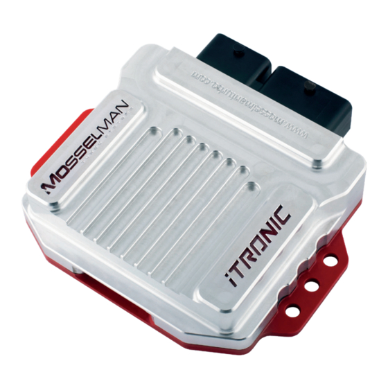
Summary of Contents for Mosselman iTronic BMW G30
- Page 1 iTRONIC Installation Manual BMW G30 B58 540i Version: 170119...
- Page 2 Installation manual for BWM models: • G30 540i Important note: Premium Fuel (Octane 98 or higher*) is highly recommended for performance increase and reliability! *Octane 93 or higher in Brazil, Canada and The United States...
- Page 3 Box Contents • iTronic engine controller • iTronic wiring harness • Installation hardware Before starting the installation of this product, please read this installation manual carefully to prevent possible damage or injuries.
-
Page 4: Table Of Contents
Table of Contents Preparing for installation Overview Installation OBD connection (optional feature) Using the iTronic Exhaust valve control (optional feature) -
Page 5: Preparing For Installation
Preparing for Installation Tools recommended for installation: - Screwdriver set - Socket set - T25 and T50 (torx) Find a suitable place for installation, preferably inside, to prevent the open connectors from getting wet. Prepare an empty space to place the parts that you temporarily have to remove from your engine bay, like the engine cover or other parts. -
Page 6: Overview
Overview *The OBD connection is used to enable additional functions and isn’t required for the basic functions of the iTronic. - Page 7 Wiring harness route *The OBD connection is used to enable additional functions and isn’t required for the basic functions of the iTronic.
-
Page 8: Installation
Installation 3.1 Remove the engine cover. • Remove the engine cover, shown in fig. 1. No tools needed for this action. 3.2 Remove the engine insulation pad. • Remove the engine insulation pad by pulling it out. No tools needed for this action. - Page 9 Installation 3.3 Connect the rail pressure sensor. • Disconnect the connector from the rail pressure sensor. • Attach the rail pressure sensor connector to the iTronic wiring harness. • Connect the connector of the iTronic wiring harness to the rail pressure sensor. 3.4 Manifold pressure sensor.
- Page 10 Installation 3.5 Chargepipe pressure sensor. • Disconnect the connector from the chargepipe pressure sensor. • Attach the chargepipe pressure sensor connector to the iTronic wiring harness. • Connect the connector of the iTronic wiring harness to the chargepipe pressure sensor. 3.6 CAN-bus connection - Remove cover.
- Page 11 Installation 3.7 CAN-bus connection - Connector. • Remove the CAN-bus connector, A46*1B 3.8 CAN-bus connection - Cables. The necessary CAN wires are yellow/white (high) and yellow/ black (low) , and are located inside the wiring loom of the first CAN-bus connector A46*1B on pin 41 & 42. The wires are twisted in a pair.
- Page 12 Installation • Open the insulation of the wiring loom to reveal the CAN- wires. Connect the high and low wire from the CAN-bus to the iTronic wiring harness, using the red clips* provided in the box. The yellow/white wire = high The yellow/black wire = low Example, not actual image! 3.9 Mass airflow sensor.
- Page 13 Installation 3.10 Ground. • Remove the round nut of the ground point, using a torx. • Connect the black -wire from the iTronic wiring harness. • Replace the round nut on the ground point, and tighten sufficiently. 3.11 Supply voltage. •...
- Page 14 Installation 3.12 Place the iTronic - Mount. 12.1 The mount is only necessary when the car is fitted without a second battery. If there is a second battery: place the iTronic on top of the battery, using the velcro tape provided in the box. •...
- Page 15 Installation 3.13 Place the iTronic. • Connect the two main connectors from the wiring harness to the iTronic. The iTronic is installed. • Secure the iTronic wiring harness using the tyraps provided in the box. Make sure there is enough clearance from hot or moving parts.
-
Page 16: Obd Connection (Optional Feature)
Optional feature: OBD connection 4.1 OBD Connector - Entry. • Remove the windshield cover. • Remove the plug shown in fig. 1. Note: Store the plug so the car can be restored into stock condition. 4.2 OBD Connector - Remove the footwell cover. Move over to the drivers seat and remove the footwell cover. - Page 17 Optional feature: OBD connection 4.3 OBD Connector. • Disconnect the OBD cable from the iTronic wiring harness. • Connect the red (16 pins) OBD connector with the connector in the car. (fig. 3). • Push the other end (2 pins connector) of the cable through the entry, created in step 4.1, into the engine bay.
-
Page 18: Using The Itronic
Using the iTronic The iTronic can be controlled, after installing it into the car, with the steering wheel buttons. This chapter will describe how to use all the additional functions of the iTronic. - Page 19 Using the iTronic 5.1 Turn the iTronic On/Off. Turn the iTronic On: • Press and hold the RES button (fig. 1) for a couple of seconds. When the iTronic is turned on the turn signals on your dashboard will light up for 3 seconds. (fig. 2) Note: The iTronic can only be controlled when the cruise control is turned off.
-
Page 20: Exhaust Valve Control (Optional Feature)
Optional Feature - Exhaust valve control 6.1 Opening the exhaust valve. • Push the cruise control scroll wheel all the way up once to open the exhaust valve. (fig. 1) 6.2 Closing the exhaust valve. • Push the cruise control scroll wheel all the way down once to close the exhaust valve. - Page 21 Notes...
- Page 22 Mosselman Turbo Systems Molenstraat 4 6732 BP, Harskamp The Netherlands +31 (0) 318 457832 info@mosselmanturbo.com www.mosselmanturbo.com /MosselmanTurboSystems @Mosselman_Turbo /MosselmanTV...
Need help?
Do you have a question about the iTronic BMW G30 and is the answer not in the manual?
Questions and answers