Table of Contents
Advertisement
Quick Links
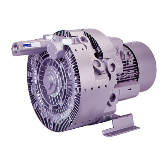
Gas-Ring Vacuum
Pumps/Compressors
Models
Single-impeller model
(single-stage)
© nash_elmo Industries GmbH
Postfach 1510
97605 Bad Neustadt / Saale
Germany
Phone:
+49 911 1454 5268
Fax:
+49 911 1454 5252
E-mail:
service@nash-elmo.com
Internet:
www.nash-elmo.com
Series G_400
2BH7 2
2BH7 3
Two-impeller model
(two-stage)
All rights reserved.
2BH7 4
2BH7 5
Three-impeller model
Order No.: 610.44436.40.000
Edition 09/2003
English
Operating
Instructions
2BH7 6
(three-stage)
Advertisement
Table of Contents

Summary of Contents for Nash Elmo G 400 Series
- Page 1 Gas-Ring Vacuum Operating Pumps/Compressors Instructions Series G_400 Models 2BH7 2 2BH7 3 2BH7 4 2BH7 5 2BH7 6 Single-impeller model Two-impeller model Three-impeller model (single-stage) (two-stage) (three-stage) © nash_elmo Industries GmbH All rights reserved. Order No.: 610.44436.40.000 Postfach 1510 Edition 09/2003 97605 Bad Neustadt / Saale English Germany...
-
Page 2: Table Of Contents
Contents Contents 1 Safety ..............................3 Definitions ..........................3 1.1.1 Safety alert symbol.......................3 1.1.2 Signal words.........................3 General safety precautions .......................3 Residual risks..........................5 2 Intended Use ............................6 3 Technical Data ............................7 Mechanical data ........................7 Electrical data..........................9 Operating conditions .........................9 4 Transport and Handling........................10 5 Installation ............................11 Installation ..........................12 Electrical connection (motor) ....................14... -
Page 3: Safety
Safety Safety CAUTION Definitions Danger of damage. To point out dangers and important Indicates a potentially hazardous situation that information, the following signal words and may result in property damage if the symbols are used in these operating corresponding measures are not taken. instructions: NOTICE 1.1.1... - Page 4 Safety WARNING WARNING When working on the pump-motor unit, Danger from rotating parts (external fan, there is a danger of injury, e.g. in the form impeller, shaft): of cuts/cutting off, crushing and burns! Cutting/cutting off of extremities, Grasping/winding up of hair and clothing! During all work on and with the pump-motor unit (transport, installation, operation, shut- Danger due to vacuum and gauge pressure:...
-
Page 5: Residual Risks
Safety WARNING WARNING Danger from rotating impeller: Danger zone: Cutting/cutting off of extremities! Fan guard The rotating impeller is accessible with the inlet Hazard: and discharge connections open! Long, loose hair can be drawn into external fan Do not reach into the unit through open through fan guard grate, even with fan guard connections! mounted! -
Page 6: Intended Use
Intended Use Increased pressure differences can be Intended Use achieved with the two-impeller and three- impeller pump-motor units. These operating instructions • are intended for industrial applications, • apply to gas-ring vacuum pumps/compressors of the G_400 series, • are primarily intended for higher pressure models 2BH7 2, 2BH7 3, 2BH7 4, 2BH7 5 conditions;... -
Page 7: Technical Data
Technical Data Minimum distance to vacuum Technical Data pump/compressor cover: Mechanical data Minimum distance to face of vacuum pump/compressor cover Weight [mm] [inches] 1.18 Single-impeller design Model Weight Vibrations [kg] [lbs] The following table provides information on the 2BH7210-0..1.-. approx. 16 approx. - Page 8 Technical Data Two-impeller design Two-impeller design (at a frequency of 50 Hz) Model 1-m measuring-surface Model Temperature increase sound pressure level L ∆T [K] [dB (A)] ∆ϑ [F] 2BH7220-0..2.-. approx. 55 approx. 131 at 50 Hz: at 60 Hz: 2BH7220-0..5.-. approx.
-
Page 9: Electrical Data
Technical Data Operating conditions Tightening torques for non-electrical connections Temperatures Thread [Nm] [ft lbs] Temperature of max. permissible temperature: 8 ± 0.8 5.9 ± 0.59 +40 °C [+104 °F] 24 ± 2.4 17.7 ± 1.77 42 ± 4.2 31 ± 3.1 Nominal value: 70 ±... -
Page 10: Transport And Handling
Transport and Handling Permissible The total pressure difference WARNING total pressure specified on the rating plate difference: only applies under the following Danger from tipping or falling loads! conditions: Prior to transport and handling make sure that • Ambient temperature: all components are securely assembled and 25 °C [77 °F]. -
Page 11: Installation
Installation For transport with a crane, the pump-motor WARNING unit can be hooked onto the crane hook as follows: Danger from balance damage caused by • directly on the eye bolt vibration! Vibrating environments can cause balance or possibly damage! •... -
Page 12: Installation
Installation Ambient conditions: CAUTION The pump-motor unit is suitable for installation in the following environments: Danger of tripping and falling! Make sure the unit does not present a danger • In a dusty or damp environment, of tripping. • in buildings, Lay cables and pipes so that they cannot be reached during operation(recessed in floor, in •... - Page 13 Installation Basically, all variants are possible with all CAUTION models. To ensure sufficient cooling of the pump-motor However, a distinction must be made between unit, also observe the following: a design with and a design without a • Ventilation screens and openings must condensed water opening for the axis remain clear.
-
Page 14: Electrical Connection (Motor)
Installation Vertical mounting on the wall CAUTION With vertical mounting of the pump-motor unit on the wall, the pump-motor unit is mounted Incorrect connection of the motor can lead to via the holes in the base. serious damage to the unit! Proceed as follows: Regulations: •... - Page 15 Installation Mount cable glands on the terminal box. DANGER Proceed as follows: • Select one cable gland in each case which Electrical danger! is suitable for the cable diameter. The terminal box must be free from • foreign bodies, • Insert this cable gland in the opening of the •...
-
Page 16: Connecting Pipes/Hoses (Vacuum Pump/Compressor)
Installation • Use screened power supply cables if necessary. For optimal screening, the screen must be conductively connected over a large area to the metal terminal box of the drive motor with a screwed metal gland. • In the case of drive motors with integrated sensors (e.g. -
Page 17: Inlet Connection
Commissioning WARNING WARNING Danger from interchanging inlet and Danger from solid bodies and impurities in pressure line! the pump-motor unit! Interchanged inlet and pressure lines can lead If solid bodies penetrate into the pump-motor to damage to the pump-motor unit and the unit, blades of the impellers can break and system, and as a result of this to serious broken pieces can be thrown out. -
Page 18: Preparation
Commissioning Measures before start-up: WARNING • If a shut-off device is installed in the discharge pipe: Danger from rotating parts (external fan, Make sure that the unit is NOT operated impeller, shaft): with the shut-off device closed. Cutting/cutting off of extremities, Grasping/winding up of hair and clothing! •... -
Page 19: Start-Up And Shut-Down
Operation Operation DANGER Electrical danger! WARNING Before beginning work on the unit or system, the following measures must be carried out: Improper use of the unit can result in • Deenergize. serious or even fatal injuries! • Secure against being switched on again. Have you read the safety precautions in •... -
Page 20: Shut-Down And Longer Standstills
Shut-Down and Longer Standstills Storage conditions CAUTION To prevent standstill damage during storage, the environment must provide the following conditions: Danger of bearing damage! Heavy mechanical impacts must be avoided • dry, during operating and while at a standstill. • dust-free, •... -
Page 21: Servicing
Servicing Servicing WARNING Improper use of the unit can result in WARNING serious or even fatal injuries! All maintenance work on the pump-motor unit Improper use of the unit can result in must always be performed by the Service serious or even fatal injuries! Department! Have you read the safety precautions in Maintenance work on the pump-motor unit may... -
Page 22: Service/After-Sales Service
Disposal Fault Cause Remedy Carried out Abnormal Flow speed too high. Clean pipes. Use pipe with larger cross- Operator flow noises. section if necessary. Muffler soiled. Clean muffler inserts, check condition and Service*) replace if necessary. Abnormal Ball bearing lacking grease Regrease or replace ball bearing. -
Page 23: 12 Declaration Of Conformity
Declaration of Conformity 12 Declaration of Conformity EC Declaration of Conformity Manufacturer: nash_elmo Industries GmbH Postfach 1510 D-97605 Bad Neustadt / Saale Product designation: Gas-ring vacuum pumps/compressors of the G_400 series, models 2BH7 2.., 2BH7 3.., 2BH7 4.., 2BH7 5.. and 2BH7 6.. The designated product complies with the provisions of the following European Directives: 98/37/EC Machinery Directive...
Need help?
Do you have a question about the G 400 Series and is the answer not in the manual?
Questions and answers