
Summary of Contents for XJTAG SPEA 3030
- Page 1 SPEA 3030 XJLink2 Carrier Board User Guide Version 1 XJTAG-3030-Guide-20C-01 enquiries@xjtag.com www.xjtag.com...
-
Page 2: Table Of Contents
SPEA 3030 XJLink2 Carrier Board . User Guide www.xjtag.com Table of Contents SECTION PAGE 1. Introduction ......................3 2. System Overview....................3 3. XJLink2-3030 Module Installation .................4 4. Carrier Board Installation..................5 5. Connecting a UUT to the Carrier Board ..............5 6. XJDeveloper Project Requirements...............6 7. -
Page 3: Introduction
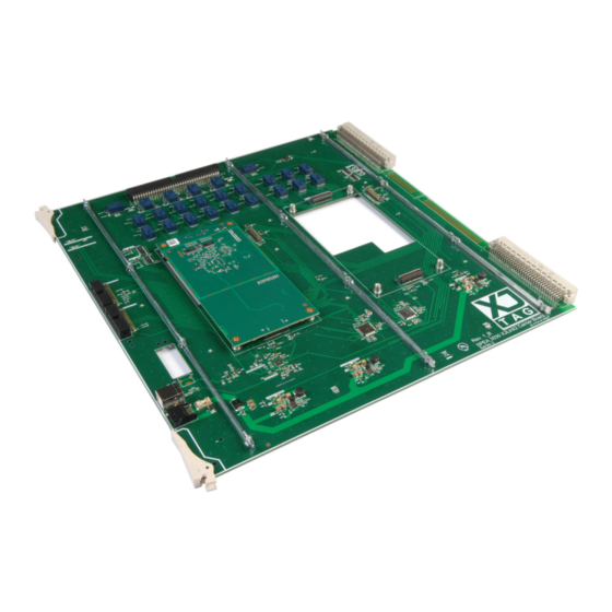
1. Introduction The SPEA 3030 XJLink2 Carrier Board, hereafter called the Carrier Board, is XJTAG’s recommended hardware solution for adding XJTAG boundary scan test capability to a SPEA 3030 bed of nails test system. System connector Stiffening bars US connector Power connector Figure 1 –... -
Page 4: Xjlink2-3030 Module Installation
SPEA 3030 XJLink2 Carrier Board . User Guide www.xjtag.com 3. XJLink2-3030 Module Installation Please follow normal anti-static handling procedures at all times. Make sure that the board stiffening bars have been fitted (see Figure 1 earlier), and that the Carrier Board is fully supported when each XJLink2-3030 module is inserted. -
Page 5: Carrier Board Installation
4. Carrier Board Installation The Carrier Board is installed into the backplane of the SPEA 3030 bed-of-nails tester. It requires separate connections for power and USB. Both of the required cables are supplied with the Carrier Board. The Carrier Board is designed to be powered by a 24 Volt supply. -
Page 6: Xjdeveloper Project Requirements
Pin 11 can be used for any other function, as a TAP pin, a general purpose I/O pin or for frequency or voltage measurement. 7. Relay Connection Sequencing When the XJTAG project is executed, either directly from XJRunner/XJDeveloper or from within SPEA Leonardo, the relays linking the system connector to the XJLink2-3030 modules are activated in a sequence. -
Page 7: Xjlink2-3030 Module Self-Test Configuration
SPEA 3030 XJLink2 Carrier Board . User Guide www.xjtag.com 8. XJLink2-3030 Module Self-Test Configuration The relays used to isolate the UUT from the XJLink2-3030 modules also provide a built-in loopback between the module pins when the Carrier Board is in its default state, i.e. not actively running tests. -
Page 8: Carrier Board Electrical And Operational Specifications
SPEA 3030 XJLink2 Carrier Board . User Guide www.xjtag.com The Loop Back Cable Fitted option is selected and greyed out as the Carrier Board will automatically apply the required loopback. When running the self-test from the integration DLL use the Test method on the XJLink object specifying a value of true for the runLoop ackTest parameter.
Need help?
Do you have a question about the SPEA 3030 and is the answer not in the manual?
Questions and answers