Table of Contents
Advertisement
Quick Links
Advertisement
Table of Contents

Related Manuals for KENT USA JHC-18S

Summary of Contents for KENT USA JHC-18S
- Page 1 www.kentusa.com 1.800.KENT.USA...
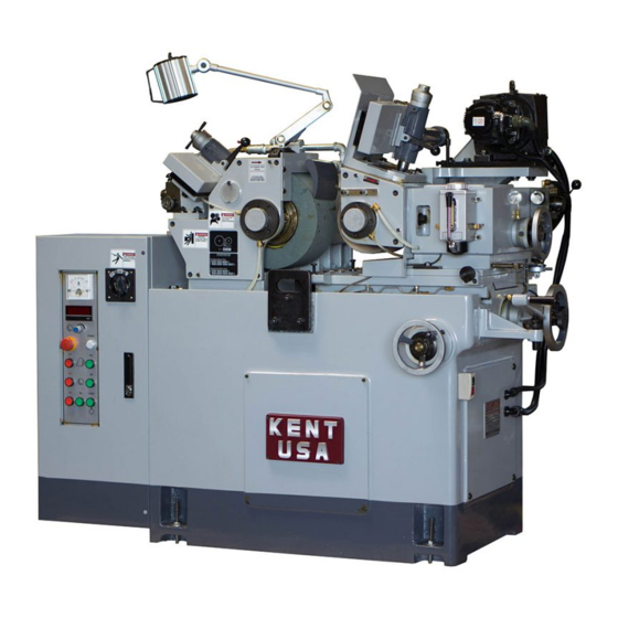
- Page 2 Operator’s Manual MACHINE NAME: CENTERLESS GRINDING MACHINE MODEL: □ JHC-12BN □ JHC-12S □ JHC-18 □ JHC-18A □ JHC-18B █ JHC-18S □ JHC-18AS □ JHC-18BS □ JHC-20 □ JHC-20S File NO :JHC-CLGM-E001 Date :2015.12.25 Version :R00 Original Instructions...
-
Page 3: Table Of Contents
CONTENTS Contents 1. SAFETY TIPS ................1-1 1.1 Warning tips ....................1-1 1.2 General safety tips ..................1-2 1.3 Machine safety tips .................1-3 1.4 Tips for electrical equipments ...............1-4 1.5 The SAMPLE AND POSITION FOR THE WARNING SIGN ..1-5 2. MACHINE SPECIFICATION ............. 2-1 2.1 JHC-12 series specification ..............2-1 2.2 JHC-18 series specification ..............2-3 2.3 JHC-20 series specification ..............2-5... - Page 4 CONTENTS 4.4 Leveling ....................4-5 4.5 Clean ......................4-6 5. MECHANISM AND ADJUSTMENT .......... 5-1 5.1 Balance of grinding wheel ..............5-1 5.2 Assemble and disassemble of grinding wheel ........5-2 5.2.1 Procedure ....................... 5-2 5.2.2 Tips: ....................... 5-8 5.3 Spindle correction ...................5-9 5.4 Grinding wheel dressing ...............5-10 5.5 Assemble and disassemble of dresser ..........
- Page 5 CONTENTS 6.6 Regulating wheel servo motor parameter list ........6-15 7. MAINTENANCE & REPAIR ............7-1 7.1 Notes of maintenance & repair ..............7-1 7.2 Period .......................7-2 7.3 Monthly check list ...................7-3 7.4 Oil-based maintenance ................7-5 7.5 Lubrication system .................7-6 7.5.1 Lubricator ...................... 7-6 7.5.2 Lubrication parts (12S.18S.20Sseries) ............
- Page 6 CONTENTS 9.3.2 Disc-plateworkpiece ..................9-5 9.3.3 Long bar workpiece ..................9-5 9.3.4 Attache-head workpiece ................. 9-6 9.3.5 Cross-shape workpiece .................. 9-6 9.3.6 Multi-size workpiece ..................9-6 9.3.7 Cone workpiece ....................9-7 9.4 Introduction of grinding wheel ..............9-8 9.5 Grinding wheel circumferential speed ..........9-13 9.6 Grinding difficulty and solution ............9-16 9.7 Spare parts .....................9-19 9.8 Size List of Grinding Wheel and Regulating Wheel ......9-23...
-
Page 7: Safety Tips
1 SAFETY TIPS SAFETY TIPS This operation manual is to decscribe how to install, operate the machine and a basicmaintenance and inspection. This manual will teach you how to operate the machine safely and correctly to make this machine work appropriately. Please read this instruction manual carefully before installation and operation. -
Page 8: General Safety Tips
1 SAFETY TIPS 7. Please stop the spindles when change / adjust the workpiece or equip / dismantle the accessories. 8. Do not use inflammable or poisonous coolant. 9. Please stop the machine immediately when find out any safe problem and ask for help from local agent. -
Page 9: Machine Safety Tips
1 SAFETY TIPS 1.3 Machine safety tips Before operating this machien, the operator must fully understand this manual. 1. The operator and service person must be pay attention to the warning sign. Do not remove or damage. 2. All guard and doors should be secured all the time except maintenace to prevent dirts entering controller. -
Page 10: Tips For Electrical Equipments
1 SAFETY TIPS 10) Clean worktable. 11) Apply lubricator on sliders and cover to prevent dust. Tips for electrical equipments Please notice below tips before maintainance and inspection. 1. Do not hit controller and pressure control board. Please use appointed wires specification which listed on manual. Wires length shouldn’t be to long. - Page 11 1 SAFETY TIPS The SAMPLE AND POSITION FOR THE WARNING SIGN...
- Page 12 1 SAFETY TIPS Warning Sign Location...
-
Page 13: Machine Specification
2 MACHINE SPECIFICATION MACHINE SPECIFICATION 2.1 JHC-12 series specification MODELS JHC-12BN JHC-12S ITEMS ψ1~ψ25mm Std work rest(dia) ψ25~ψ40mm Special work rest(dia) ψ305×150×ψ120 Grinding wheel size(dia×width×hole) ψ205×150×ψ90 Regulating wheel size (dia×width×hole) Grinding wheel speed 1900 R.P.M 20-337 R.P.M 10-300 R.P.M Regulating wheel speed (7 step) Stepless Grinding wheel motor... - Page 14 2 MACHINE SPECIFICATION MODELS JHC-12BN JHC-12S ITEMS 7mm(Rev) Table feed on handwheel 0.05mm(Gra) 0.2mm(Rev) Table micro feed on handwheel 0.001mm(Gra) 1.25mm(Rev) Dressing handwheel 0.01mm(Gra) +5°~-3° Regulating wheel tilt angle Regulating wheel swivel angle ±5° 1800×1400×1400mm Machine size (L×W×H)( approx) Net weight (approx) 1600kgs Shipping gross weight (approx) 1750kgs...
- Page 15 2 MACHINE SPECIFICATION 2.2 JHC-18 series specification MODELS JHC-18 JHC-18S JHC-18A JHC-18AS JHC-18B JHC-18BS ITEMS ψ1~ψ50mm Std work rest(dia) ψ40~ψ100mm Special work rest(dia) Grinding wheel ψ455×205×ψ228.6 ψ455×255×ψ228.6 ψ455×305×ψ228.6 size(dia×width×hole) Regulating wheel size ψ255×205×ψ111.2 ψ255×255×ψ111.2 ψ255×305×111.2 (dia×width×hole) Grinding wheel speed 1500 R.P.M 13-316 R.P.M...
- Page 16 2 MACHINE SPECIFICATION MODELS JHC-18 JHC-18S JHC-18A JHC-18AS JHC-18B JHC-18BS ITEMS 9mm(Rev) Table feed on handwheel 0.05mm(Gra) 0.2mm(Rev) Table micro feed on handwheel 0.001mm(Gra) 2mm(Rev) Dressing handwheel 0.01mm(Gra) +5°~-3° Regulating wheel tilt angle Regulating wheel swivel angle ±5° 2300×2000×1530mm Machine size (L×W×H)approx)
-
Page 17: Series Specification
2 MACHINE SPECIFICATION 2.3 JHC-20 series specification MODELS JHC-20 JHC-20S ITEMS ψ1~ψ50mm Std work rest(dia) ψ40~ψ100mm Special work rest(dia) ψ510×205×ψ254 Grinding wheel size(dia×width×hole) ψ305×205×ψ127 Regulating wheel size (dia×width×hole) Grinding wheel speed 1350 R.P.M 13-316 R.P.M 10-250 R.P.M Regulating wheel speed (10 step) stepless Grinding wheel motor... - Page 18 2 MACHINE SPECIFICATION MODELS JHC-20 JHC-20S ITEMS 0.2mm(Rev) Table micro feed on handwheel 0.001mm(Gra) 2mm(Rev) Dressing handwheel 0.01mm(Gra) +5°~-3° Regulating wheel tilt angle Regulating wheel swivel angle ±5° 2300×2000×1530mm Machine size(L×W×H)(approx) Net weight (approx) 3200kgs Shipping gross weight (approx) 3500kgs 3200×1400×1900mm Packingsize(L×W×H) (approx)
-
Page 19: Machanism And Part List
2 MACHINE SPECIFICATION Machanism and part lis... - Page 20 2 MACHINE SPECIFICATION NAME NAME...
- Page 21 2 MACHINE SPECIFICATION Grinding wheel dresser Electric box Grinding wheel dressing Leveling screw emergency return handle Dressingcontrol for grinding Grinding wheel wheel Blade Workrest Regulating wheel fixed screw Lower slider (worktable) Nut for regulating wheel swivel Up slider angle Handle for grinding wheel Micro feeding handwheel for feeding worktable...
-
Page 22: Parts Function
2 MACHINE SPECIFICATION Parts function 1) Grinding wheel dresser: dress grinding wheel. 2) Grinding wheel dressing emergency return handle: avoid damage t ogrinding wheel by carelesness or human erros. 3) Grinding wheel: grinding workpiece. 4) Blade: Suppor t workpiece. 5) Regulating wheel fixed scrw: one on left and the other on right side to fix regulating wheel. - Page 23 2 MACHINE SPECIFICATION handwheel is functioned. 17) Nut for regulating wheel swivel angle: adjust the horizontal swivel angle of regulating wheel. 18) Oil tank: where tostoreoil. 19) Grinding wheel driving motor: grinding wheel rotating power source. 20) Electric box: controlling electricity and electric circuit 21) Leveling screw: adjust machine leveling 22) Dressingcontrol for grinding wheel: control the speed and direction.
-
Page 24: Standard Accessories
2 MACHINE SPECIFICATION 2.6 Standard accessories MODE STANDARD ACCESSORIES 1. Grinding wheel and flange 2. Regulating wheel and flange 3. Thrufeedworkrest and blade 4. Infeedworkrest and blade 5. Tool box and tool 6. Working lamp 7. Diamond dresser *2 8. Thrufeed safety device 9. -
Page 25: Optional Accessories
2 MACHINE SPECIFICATION 2.7 Optional accessories MODE OPTIONAL ACCESSORIES 1. Magnetic seperator 2. Paper filter 3. Hydrocyclonecooloont filtering unit 4. Work ejector device 5. Forming dressing device 6. Long V-shaped support 7. Manual parts feeder for infeed grinding 8. Automatic receiver for thrufeed grinding 9. -
Page 26: Machine Layout
3 MACHINE LAYOUT MACHINE LAYOUT 3.1 Floor space (Unit:mm) MODEL JHC-12 JHC-18 JHC-20 SIZE 1800 2300 2300 1400 2000 2000... -
Page 27: Transportation & Installation
4 TRANSPORTATION & INSTALLATION TRANSPORTATION & INSTALLATION Lifting... -
Page 28: Transportation
4 TRANSPORTATION & INSTALLATION Transportation 4.2.1 Center-of-gravity position of forklift and machine Models JHC-12 JHC-18 JHC-20 C(mm) -
Page 29: Position Offorklift Transportation
4 TRANSPORTATION & INSTALLATION 4.2.2 Position offorklift transportation... -
Page 30: Foundation
4 TRANSPORTATION & INSTALLATION 4.3 Foundation The machine should be installed on rigid and plant floor. It’s recommended to use concrete of at least 150mm thickness at the place installing the machine and to keep from source of vibration, such as punching or planer. It would be better to use vibration-isolated equipment at the foundation. -
Page 31: Leveling
4 TRANSPORTATION & INSTALLATION 4.4 Leveling The level of machine will be regulated after machine installed for 24 hours. The level precision of machine is subject to change by temperature and other factors. Hence, it should be re-leveling once a year to ensure its precision. Each graduation of level should be 0.02mm/m. -
Page 32: Clean
4 TRANSPORTATION & INSTALLATION 4.5 Clean For shipment by ocean to user’s factory, it has to use anti-rust oil spreading overall machine for protection. When take the plastic cover off machine. Please use soft cloth with kerosene to clean machine body and then put either oil or grease on parts which need to be lubricated before running the machine. -
Page 33: Mechanism And Adjustment
5 MECHANISM AND ADJUSTMENT MECHANISM AND ADJUSTMENT Balance of grinding wheel Balance of grinding wheel is to obtain good smoothness and accuracy of workpiece after grinding and to keep machine in equilibrium condition. The mark caused by tremble appearing on the surface ofworkpiece is owing to vibration. This kind of deformation can be seen by eyes. -
Page 34: Assemble And Disassemble Of Grinding Wheel
5 MECHANISM AND ADJUSTMENT Assemble and disassemble of grinding wheel 5.2.1 Procedure Show as figures: (base different models) - Page 35 5 MECHANISM AND ADJUSTMENT...
- Page 36 5 MECHANISM AND ADJUSTMENT JHC-12disassemble procedure Step 1 (Fig. 1) 1. Seperate 2 oil pipes connect to alloy bearing housing. 2. Dismantle cover screw and pin. Step 2(Fig. 2) 1. Take out oilseal bush. 2. Loose grinding wheel locked nut along with clockwise direction for 2-3 cycles by spanner (do not draw out completely) 3.
- Page 37 5 MECHANISM AND ADJUSTMENT Step 3(Fig. 3) 1. Draw out screw on flange cover and seperate grinding wheel and flange. 2. Follow the above actions in reverse sequence to install back. Fig. 3...
- Page 38 5 MECHANISM AND ADJUSTMENT -18disassemble procedure Step 1(Fig. 1) 1. Seperate 2 oil pipes connect to alloy bearing housing. 2. Dismantle cover screw and pin. Step 2(Fig. 2) 1. Take out oilseal bush. 2. Loose grinding wheel locked nut along with clockwise direction for 2-3 cycles by spanner (do not draw out completely) 3.
- Page 39 5 MECHANISM AND ADJUSTMENT Step 3 (Fig. 3) 1. Mount grinding wheel loading and unloading tube. 2. Dismentle the grinding wheel slightly. Step 4 (Fig. 4) 1. Draw out screw on flange cover and seperate grinding wheel and flange. 2. Follow the above actions in reverse sequence to install back.
-
Page 40: Tips
5 MECHANISM AND ADJUSTMENT 5.2.2 Tips: 1) All dismentaled parts should be cleaned and lubricated. 2) All assembled contact surfaces should be coated with grease. 3) Parts between grinding wheel and flange should be coated with anti-rust grease or paved with a coat of tinfoil for the conveninece of disassembling next time. -
Page 41: Spindle Correction
5 MECHANISM AND ADJUSTMENT Spindle correction Upon replacing grinding wheel or regulating wheel, thedeflection of spindle must be corrected to ensure grinding precision. As below Fig. shown, place 1/1000mm gauge (1) on wroktable with gauge needle being leant against circumference of spindle with proper pressure where all contact surface msut be cleaned. -
Page 42: Grinding Wheel Dressing
5 MECHANISM AND ADJUSTMENT Grinding wheel dressing The dressing of grinding wheel almost utilizes single diamond tool method. The size of diamond is subject to dress grinding wheel’s diameter and binding degree, but commonly 500-600mm grinding wheel employs 1-2 carat of diamond tool. To avoid vibration when erecting, diaond tool should be completely fixed on feed shaft and the distance from its fixed part to the nose of it must be reduce as much as possible. -
Page 43: Assemble And Disassemble Of Dresser
5 MECHANISM AND ADJUSTMENT Assemble and disassemble of dresser 5.5.1 Procudure As figures(Base different models) -12 series dresser combination 1. Feeder 2. Feed spindle 3. Hexgon socket fixed screw 4. Diamond tool 5. Hexgon socket fixed screw 6. Feed spindle housing 7. - Page 44 5 MECHANISM AND ADJUSTMENT Assemble and disassemble procedure: 1) Loose locked nut (10) and slightly knock serveral times inward to make locked bolt (8) loss feed spindle (2). 2) Draw out Hexagon socket bolt (7). 3) Release Hexgon socket fixed screw (5) and draw out feed spindle (2) through feeder (1).
- Page 45 5 MECHANISM AND ADJUSTMENT -18 series dresser combination 1. Hexgon socket fixed bolt 2. Feeder 3. Feed spindle 4. Hexagon socket fixed screw 5. Diamond tool 6. Feed spindle housing 7. Hexagon socket bolt 8. Locked bolt 9. Locked sleeve 10.
- Page 46 5 MECHANISM AND ADJUSTMENT 5.5.2 Tips 1) Dismantled parts should be cleaned and lubricated. 2) Diamond dresser protruding length is about 15 ~ 20 mm. 3) When install back hexgon socket fixed bolt (1), need to align the keyway of feeding axis.
-
Page 47: Intoduction Of Regulating Wheel
5 MECHANISM AND ADJUSTMENT Intoduction of regulating wheel 5.6.1 Regulating wheel feed mechanism When grinding wheel is fixed, the grinding of workpiece depends on the movement of regulating wheel slide. That is, the travel of regulating wheel slide and lower slide would regulate distances between regulating wheel, grinding wheel and blade. - Page 48 5 MECHANISM AND ADJUSTMENT 5.6.2 Spindle position adjustment of regulating wheel In thrufeed grinding, the vertical angle of regulating wheel can be inclined +5˚ to -3˚ which is adjusted base on feeding speed. While failing to line up grinding wheel owing to adjustment of vertical angle, you must line them up as below figure.
- Page 49 5 MECHANISM AND ADJUSTMENT 5.6.3 Assemble and disassemble of regulating wheel 1. Procedure (as below fig. shown): JHC-12 series regulating combination JHC-18 series regulating wheel combination 5-17...
- Page 50 5 MECHANISM AND ADJUSTMENT 2. Note: 1) All disassemble parts should be cleaned and lubricated. 2) All assembled contact surfaces should be coated with grease. 3) Parts between regulating wheel and flange should be coated with anti-rusting grease or paved with a coat of tinfoil for the convenience of disassembling next time.
- Page 51 5 MECHANISM AND ADJUSTMENT JHC-12 series assemble and disassemble procudre Step 1(Fig. 1) 1. Separate 2 oil pipes connected to alloy bearing seat. 2. Dismantle end cover plate screw and positioning pin. Step 2(Fig. 2) 1. Take out oil seal bush. 2.
- Page 52 5 MECHANISM AND ADJUSTMENT Step 3 (Fig. 3) 1. Draw out screw on flange cover from and seperate flange and regulating wheel. 2. To install back base on above mentioned action in reverse order. Fig. 3 5-20...
- Page 53 5 MECHANISM AND ADJUSTMENT JHC-18 series assemble and disassemble procedure Step 1 (Fig. 1) 1. Separate 2 oil pipes (1) from alloy bearing seat (2). 2. Dismantle positiong pin (4) and fixing bolt (5), then, take out cover (6). Step 2 (Fig.
- Page 54 5 MECHANISM AND ADJUSTMENT Step 3 (Fig. 3) 1. Draw out screw on flange cover and separate flange and regulating wheel. 2. To install back base on to above mentioned action in reverse order. 5.6.4 Speed of regulating wheel 5-22...
- Page 55 5 MECHANISM AND ADJUSTMENT The roating speed of regulating wheel range is from 10 to 300rpm, and dressing range is 300rpm. Grinding speed is subject to change by (1) the axial feed speedand the circumferential speed (2) of workpiece. Generally, grinding rotating speed of grinding range is from 20 to 40rpm.
- Page 56 5 MECHANISM AND ADJUSTMENT higher rotating speed. Although alter regulating wheel’s slant angle may adjust workpiece axial feed speed. It’s no recommended because correcton must be made up changing slant angle. Besides, be noticed that correction both on workpiece’s circumferential aspeed and correcting grinding conditon. 5-24...
- Page 57 5 MECHANISM AND ADJUSTMENT 5.6.5 Dress on regulating wheel While dressing regulating wheel, the condition of diamond tool and coolant is similar to dress grinding wheel. However, the dressing rotating speed of regulating wheel is approximately 325rpm so in rough grinding, the dressing speed is 40 to 50 mm/min. As to the speed of finish grinding is similar to that of grinding wheel.
- Page 58 5 MECHANISM AND ADJUSTMENT 5.6.6 Slant angle adjustment of regulating wheel 1. Loose lock nuts (2) (3). 2. Rotate regulating bolt (1) to make regulating wheel slant transversely where slant scale can be shon from angle indicator (4). 3. Upon regulating to required angle, lock (2) and (3). 5-26...
- Page 59 5 MECHANISM AND ADJUSTMENT 5.6.7 Swivel angle of regulating wheel 1. Loose lock nuts (2) (both sides). 2. Rotate regulating handscrew (1) properly to swive regulating wheel horizontally. 。 Note: JHC-12 series have handscres each one for both sides. When adjusting, rotater right on one side and left turn is made on the other sidel.
-
Page 60: Workrestand Blade Support
5 MECHANISM AND ADJUSTMENT and blade support Workrest 5.7.1 Workrest Infeed grinding workrest& blade Thrufeed grinding workrest& blade 5-28... -
Page 61: Blade
5 MECHANISM AND ADJUSTMENT 5.7.2 Blade The support blade in common is 60∘. There is more wear in the part of frequenet contact on workpiece due to the load of grinding resistance. Gernerally, blade is welded with super-hard wolfram shell; sometimes high speed steel is used. -
Page 62: Ejection And Adjustment Workrest Andblade
5 MECHANISM AND ADJUSTMENT 5.7.3 blade Ejection and adjustment workrest and Put blade (1) intoworkrest(2) to a proper position. Lock fixed bolts (3) on two sides to fix blade (1). Place workrest on worktable (5), measure the required positon and turn feed handwheel in worktable (5) to move balde near grinding wheel (6). -
Page 63: Adjustment Of Thrufeed Guide Plate
5 MECHANISM AND ADJUSTMENT Adjustment of thrufeed guide plate The regulation of thrufeed guide plate is show (fig. 1). Turn regulating screw (2) by screwdreiver (1) to make guide plate (3) close or open to match workpiecesize where regulating scale is shown on (fig. 1). The guide plate should be parrallel to both grinding wheel and regulating wheel and the entry of regulating wheel’s edge is 1/2 tolerance of workpiece. -
Page 64: Operation
6 OPERATION 6. OPERATION 6.1 Operation key description A. Panel description: 40 60 80 100 0000 POWER (10) (13) (12) (11) START... - Page 65 6 OPERATION Chart1 Operation key description DESCRIPTION Power switch: ON: turn on power OFF: turn off power POWER Power on indicator Load current indicator: 40 60 80 100 When grinding wheel spindle starts and grinds, it display the current of motor. 0000 Regulating wheel spindle rotation number indicator Regulating wheel rotation number control knob:...
- Page 66 6 OPERATION DESCRIPTION Turn off switch of regulating wheel motor START Hydraulic start switch Coolant start switch Coolant stop switch...
- Page 67 6 OPERATION Chart 2 JHC-12BN: regulating wheel tachometer regulating wheel tachometer Handle R.P.M Handle R.P.M...
- Page 68 6 OPERATION Chart 3 JHC-18.18A.18B.JHC-20: regulating wheel tachometer regulating wheel tachometer Handle R.P.M Handle R.P.M...
- Page 69 6 OPERATION Regulating wheel variable operation steps For example: tachometer A-1 1. Pull up handle (1) and move to A, then, insert and fix. 2. Pull up handle (2) and move to 1, then, insert and fix. 3. Other revolutions base on tachometer to coordinate rpm.
- Page 70 6 OPERATION Auto-grinding operation panel description: (optional))
- Page 71 6 OPERATION Chart 4 Auto-grinding operation panel key descriptions DESCRIPTION POWER 電源 Power on indicator Off mode selectoin Operate robot arm to elevate and lower MANUAL slide feeding manually. Press AUTO START to do once AUTO atuo-grinding cycle. Press AUTO START to do continual CONTINUAL auto-grinding cycle.
- Page 72 6 OPERATION ENABLE(optional) Please press “ENABLE” to do the security scanning process under the safe-mode, after confirming the correct then control loop will start accordingly.
-
Page 73: Machine Switch Off Procedure
6 OPERATION 6.2 Machine switch off procedure 6.2.1 Operaton panel 1. Turn the switch (1) of electric box door ON. 2. Emergency stop switch (6) is pushed. 3. Release emergency stop switch (6) and POWER indicator (2) lights on. 4. Push STARTswitch (11) to start hydaulic pump motor and hydraulic actuation system begins. -
Page 74: Auto Griding Operation Panel
6 OPERATION Note: The procedure for stop regulating wheel rotation of JHC-12BN.18.18A.18B.20 is as below. 1. Base on the steps of regulating wheel gear box tachometer to choose rotation number. 2. Press regulating wheel motor start switch ON (9) to start regulating wheel spindle. -
Page 75: Switch Of Proximal Regulating Wheel Motor
6 OPERATION 6.2.3 Switch of proximal regulating wheel motor 1. Set the grinding terminal by regulating wheel motor switch (22) which locates under auto feeding knob.Press green button is to start regulating spindle. Press red button is to stop regulating wheel. Machine switch off procedure 1. -
Page 76: Cable Connection And Trial Run
6 OPERATION 6.4 Cable connection and trial run Connect auto lubrication motor, coolant motor and power. The green cable of four core cable is grounding wire. Machine, coolant storage tank and oil tank should be grounded to prevent operators get electric shock when electric leakage happens. Buttons in electric box have interlock function. -
Page 77: Working Lamp Replacement
6 OPERATION Working lamp replacement Unscrew the cover in advance and take out, then, release screw of reflector and take out to replace lamp. The workping lamp specification is 12V、55W. 6-14... -
Page 78: Regulating Wheel Servo Motor Parameter List
6 OPERATION 6.6 Regulating wheel servo motor parameter list PARAMETER DEFINITION UNIT SETTING REMARK Servo motor Pn000.0 Basic rotationg function Direction Pn000.1 selection Pn000.2 Spindle position switch Pn000.3 Spare WehnSERVO Pn001.0 OFF, motor stop mode selection Basic Overtravel stop Pn001.1 function mode Stop freely... - Page 79 6 OPERATION N-OT signal Pn50B.0 formed /ALM-RST Pn50B.1 Input signal formed signal /P-CL signal selection1 Pn50B.2 formed /N-CL signal Pn50B.3 formed The power of the external Pn600 JHC-12 series regenerative resistor The power of the external Pn600 JHC-18/20 series regenerative resistor The power of the external Pn600 JHC-18BS/24series...
-
Page 80: Maintenance & Repair
7 MAINTENANCE & REPAIR 7. MAINTENANCE & REPAIR 7.1 Notes of maintenance & repair 1) Prevent using non-appinted, unknown quality and source oil. 2) Clean and mainten machine and turn off machine power (power switch on electric box door) after duty off. 3) Maintein machine after machine stops completely or pwer is shutdown to prevent danger happens. -
Page 81: Period
7 MAINTENANCE & REPAIR Period ITEM CYCLE CONTENT Oil volume and pressure of Each Oil volume should be within scale table and rinding wheel oil tank pressure should be 8~10kg/cm². Oil volume of manual Each Oil volume should be within scale table. oiltank Each Coolant volume... -
Page 82: Monthly Check List
7 MAINTENANCE & REPAIR 7.3 Monthly check list Descript Item 1. Rust or damage on two spindles 2. Safety on protector cover or not 3. Rust or damage on the joint face 4. Damage on oil scraper or not Appearance 5. - Page 83 7 MAINTENANCE & REPAIR Descript Item 6. Change oil regularly 7. The pressure is normal 8. Vibration or not on the pressure gauge Lubrication, hydraulic oil 9. Leaking or not on cylinder and device 10. Leaking from pipe connector, switch or not 11.
-
Page 84: Oil-Based Maintenance
7 MAINTENANCE & REPAIR Oil-based maintenance 1) Poor quality of hydraulic oil affects machine a lot, please renew oil immedaitely. 2) All filter of pump suction side must keep clean and smooth and maintain periodically. 3) Main reason for leaking is poor gasket, please replace new one at any time. Open cavities of hydraulic circuit to exclude air to prevent noise and vibration. -
Page 85: Lubrication System
7 MAINTENANCE & REPAIR Lubrication system 7.5.1 Lubricator Whetehr the use of lubricator is correct or the cycle of lubricator incresement (or change oil) issame as the chart influence machine life and accuracy. Hence, please purchase lubricator form reliable oil supplier in accordance with the chart shown below. - Page 86 1st:3 months regulating wheel 15 gallon, than 80mm from R-12 or : 6 months spindle, JHC-18S.20S surface of barrelf, ESSO : 12 months auto-lubrication and about 25 gallon oil must be added SPINESSO.10. dressing oil to requrked 。...
- Page 87 7 MAINTENANCE & REPAIR 1. Oil of the same grade from other brand is available also. 2. Increase (change) oil cycle is based on the period of 8 hours per day.
-
Page 88: Lubrication Parts (12S.18S.20Sseries)
7 MAINTENANCE & REPAIR 7.5.2 Lubrication parts (12S.18S.20Sseries) Fig. 1 1. Regulating wheel micro feed bearing 2. Worktable micro feed bearing 3. Regulating wheel feed bearing and screw 4. Worktable feed bearing and screw 5. Rail of slide 6. Plane of revolution on lower slide 7. -
Page 89: Lubrication Parts (12Bn.18.18A.18B.20 Series)
7 MAINTENANCE & REPAIR 7.5.3 Lubrication parts (12BN.18.18A.18B.20 series) Fig. 2 1. Regulating wheel micro feed beawring and screw 2. Worktable micro feed bearing 3. Worktable feed bearing and screw 4. Rail of slide 5. Plane of revolution on lower slide 6. - Page 90 7 MAINTENANCE & REPAIR Fig. 3 7-11...
-
Page 91: Hydraulic System
7 MAINTENANCE & REPAIR Hydraulic system 7.6.1 Hydraulic circuit Ⅰ ) Parts list ITEM ITEM ITEM Oil tank Flow control valve Flow control valve Filter(3/4”) Grinding oil lens Direction change lever Motor Grinding wheel Dressing oil cylinder Regulating wheel Hydraulic pump Flow control valve oil lens Stop valve... -
Page 92: Hydraulic Pressure Adjustment
7 MAINTENANCE & REPAIR 7.6.2 Hydraulic pressure adjustment Auto lubricaton and hydraulic dressing devices for grinding wheel spindle and regulating wheel spindle are used with same pump. Generally, oil pressure should be kept at 8-10kg / cm . If pressure is higher than capacity of oilseal, oil will leak. -
Page 93: Flow Adjustment
7 MAINTENANCE & REPAIR 7.6.3 Flow adjustment Flow control valve is to regulate oil capacity into grinding wheel spindle and regulating wheel spindle and to keep normal oil pressure and capacity so that lubrication and cooling system may obtain high efficiency. The adjusting way is to follow mark direction on hand screw, turn right is to reduce flow and turn left is to increase flow. -
Page 94: Coolant Selection
7 MAINTENANCE & REPAIR 7.7 Coolant selection Coolant is to get flush grits of binding agent and chips from both grinding wheel and regulating wheel quickly. It can cool workpiece, reduce friction between workpiece and grinding wheel and enhance surface glazing on workpiece. Coolant flows from tank through pump to machine, then back to coolant tank and flow through some deposit tanks to get rid of sands, bonding agent and chips to recycle. - Page 95 7 MAINTENANCE & REPAIR and permeability are less good. 3) Transparent water-solubility coolant Mainly with chemical treatment chrome acid sodium such as inorganic ammonium, dissolves into water and apears transparent which develops anti-solubility and resst prevention with good grinding effect. It’s suitable for cast iron and cast steel.
-
Page 96: Trouble Shooting
8 TROUBLE SHOOTING 8. TROUBLE SHOOTING Common cause & remedy ABNORMAL CAUSE REMEDY 1. Lack of power supply. Check power 2. No fuse switch (NFB) off. Turn NFB to ON Turn on power, power indicator no 3. Power lamp isn’t bright. Repair power lamp. - Page 97 8 TROUBLE SHOOTING 4.Pump impeller is worn out. Replace new parts. 5. Motor is bun. Replace new parts. Add appointed or same specification 1. Oil level is too low. oil. Check filter and pipe is stuck by 2.Pump inlet pipe is stuck. obstructions or not.
-
Page 98: Grinding Application
9 GRINDING APPLICATION 9. GRINDING APPLICATION Centerlessgrinding principle Centerless grinding means no need to clamp workpiece for griding. The grindingmethod is as figure shown. It’s consisting of grinding wheel, regulating wheel and work rest. Grinding wheel is used for grinding, regulating wheel for controling rotation workpieces and enable its rotation to be teh same as feed speeed. - Page 99 9 GRINDING APPLICATION but it is not a real circle, its a triangle-like or quadrangle like-circle. If workpiece is put on the highter place than connecting line between centers of two griding wheels, when bevel point on workpiece contacts regulating wheel , the point pressing against grinding wheel doesn’t symmetrize it.
-
Page 100: Centerless Grinding Method
9 GRINDING APPLICATION Centerless grinding method 9.2.1 Thrufeed method Grinding is made by passing workpiece through two grinding wheels meanwhile. Regulating wheel is made to an inlcination fora applying its component of velocity in cirucumferentical speed. To guide workrpiece to the correct grinding position, four guide plates are placed in front of and rear of blade. -
Page 101: Infeed Method
9 GRINDING APPLICATION 9.2.2 Infeed method The grinding method is firstly, workpiece is sent from two sides or top of two grinding wheels into the required position, then, move regulating wheel forward to grind which is a kind of radial feed method, suitable for complicated conical workpiece machining. -
Page 102: Grinding Method For Different Workpiece
9 GRINDING APPLICATION Grinding method for different workpiece There is a wide selection of shapeds on workpieces for centerless grinding. Here aresome samples and popular grinding methods. 9.3.1 Short circle workpiece If no other cause, generally by thrufeed grinding, especially for auto feeder with economical efficiecency (short and small workpiece the best) Continuous feeding workpiece in thrufeedgridning is important as size variation can occur with interitting feeding. -
Page 103: Attache-Head Workpiece
9 GRINDING APPLICATION 9.3.4 Attache-head workpiece Infeed grinding method is employed when the external diameter of grinding part is smaller than head part. When its center of gravity is on the grinding part, workpece is sent into nearly-contact positon between bid head end face and two wheel’s end face for feeding and grinding. -
Page 104: Cone Workpiece
9 GRINDING APPLICATION three different diameters on grinding part, better limit with two grinding parts. For curve part and void slot not ground, it is difficult for grinding wheel to dress double grinding wheels with spare betwen. 9.3.7 Cone workpiece The workpiece only with cone not emphasized its concentricity, grinding is made in accordance with the folloing ways. -
Page 105: Introduction Of Grinding Wheel
9 GRINDING APPLICATION Introduction of grinding wheel Selection of grinding wheel: Tor desireable grinding process, grindignwehel is selected bvase on workpiece’s requirement and machine’s grinding feature. The consideraton must also include selecting proper roughness degree, binding degree, texture and binding agent. A. - Page 106 9 GRINDING APPLICATION workpiece. Hard material, such as hardened steel and special steel, hard and tough “WA” grit is adapted instead of “A” grit. For general cast iron, brass, copper, tin and tungsten materials, “C” grit is applied. “A’ grit, however, with high hardness and high selt-generating fucntion, may prevent lip of grit from being buried.
- Page 107 9 GRINDING APPLICATION B. Roughness degree Roughness degree is classified as shown as below. . No of 10,12,1416, 70,80,90,100,12 240,280,320,400,500 30,36,4654,60 roughness 20,24 0150,180,220 ,600,700,800 Coarse Medium Fine Very fine The sizes of various grits are given below Type Coarse Medium Fine Very fine...
- Page 108 9 GRINDING APPLICATION C. Binding agent Binding agent includes Vitrified(V), Silicate(S), Rubber(R), Resinous(B), Shellac(E) and metal (M). Vitrified is the hardest and strong binding agent, only very few amount would obtain would obtain high hole rate to required bindng degree with very few clogs on grinding wheel. The bound wheel is very sharp and has high strength.
- Page 109 9 GRINDING APPLICATION E. Texture The density of grinding wheel in unit volum is called texture. There are three stages in JIS: rough, medium and dense. The function of texture is to discharge chips. Its effect has close relation with binding degree. The following items are the rules for selecting texture: 1.
-
Page 110: Grinding Wheel Circumferential Speed
9 GRINDING APPLICATION Grinding wheel circumferential speed The higher circumferential speed of griding wheel is reached, the better grinding efficiency and finishing surface is obtained. But grinding wheel circumferential speed is limited by the strength of binding agent. Generally speaking,centerless grinding machine circumferential speed is around 1800m / min. - Page 111 9 GRINDING APPLICATION Selection of grinding wheel Hardness of Grinding material Recommended types material General structure rolled steel (SS) A 60M <HRC25 Mechanical struture carbon steel(SC) 38A 60L (S-CK) Structure carbon steel iron pipeSTK) >HRC25 Carbon steel wrough work(SF) WA 60L Carbon steel cast work(SC)...
- Page 112 9 GRINDING APPLICATION Bronze (BC) A 60M WA 60K Material for permanent magnet cast C 60L magnet CGC 60L 9-15...
-
Page 113: Grinding Difficulty And Solution
9 GRINDING APPLICATION Grinding difficulty and solution There are various phenomeons and difficulties occured in centerless grinding work, the following table show their reasons and solution. In fact, a problem resulte from many reasons and come with serverlsolutoins in which each otehr has relativity. Hence, the folloingseasure is notthe only way to settle problem. - Page 114 9 GRINDING APPLICATION 1. Reduce center height. 1. Center is too high. 2. Reduce angle. 2. The angle of blade is too large. 3. Increase thickness. 3. The blade is too thin. 4. Relock screw. 4. The blade isn’t equipped well. 5.
- Page 115 9 GRINDING APPLICATION 1. Make guide plate parellel. 2. Increase tilt angle of 1. Undesirable regulation of grindingwheel. Low contral part guideplate. 3. Reduce swivel angle of regulaitng wheel on dressing device . 1. More deformation before grinding. Fail to get real 2.
-
Page 116: Spare Parts
9 GRINDING APPLICATION Spare parts JHC-12S series SPECIFICATI LOCATION NAME Q’TY REMARK TC45、62、9 Oil seal End cover alloy O ring bearing seat O ring TC75、95、 Oil seal Spindle front cover O ring TC60、75、9 Oil seal Spindle rear covedr O ring Center rest Thrust bearing 51111... - Page 117 9 GRINDING APPLICATION Feed beawring seat Thrust bearing 51106 Feed bearing seat Thrust bearing 51107 Ball screw 6006Z bearing Micro adjust feed Automatic bearing seat 1206 alignment bearings O ring Cylinder cover O ring Piston O ring O ring 4033 Filter O ring P105...
- Page 118 9 GRINDING APPLICATION JHC-18S、18AS、18BS、20S series LOCATION NAME SPECIFICATION Q’TY REMARK TC65、95、14 Oil seal End cover alloy O ring bearing seat O ring TC105、135、14 Oil seal Spindle front cover O ring TC80、105、13 Oil seal Spindle rear cover O ring Thrust...
- Page 119 9 GRINDING APPLICATION Thrust Feed bearing seat 51106 bearing Micro feed bearing Thrust 51106 seat bearing Thrust Feed bearing seat 51109 bearing Micro feed bearing Thrust 51107 seat bearing O ring P65A Feed bearing seat O ring Piston O ring P48A O ring 4033...
-
Page 120: Size List Of Grinding Wheel And Regulating Wheel
9 GRINDING APPLICATION Size List of Grinding Wheel and Regulating Wheel ψD ψH JHC-12 series JHC-18 series 228.6 JHC-18A series 228.6 JHC-18B series 228.6 JHC-20 series ψD ψH JHC-12 series JHC-18 series 111.2 JHC-18A series 111.2 JHC-18B series 111.2 JHC-20 series 9-23...
Need help?
Do you have a question about the JHC-18S and is the answer not in the manual?
Questions and answers