Table of Contents
Advertisement
Quick Links
Advertisement
Table of Contents

Summary of Contents for ROSTSELMASH Strige ZTT-2.1
- Page 3 Rotary mower “Strige” Operation manual Version 2...
- Page 4 CAUTION! MOST IMPORTANT! is intended for bevelling of herbs in mowing strips in all zones of flat land use on fields The mower with the leveled relief. Any other usage is to be a misuse. The Manufacturer is not responsible for any damage hereupon.
- Page 5 DECLARATION OF CONFORMITY ЕС MANUFACTURER: JSC “KLEVER” 2-6/22, 50-letiya Rostselmasha Street Rostov-na-Donu, 344065, Russia Phone: + 7 (863) 255-22-00 AUTHORISED REPRESENTATIVE in EU: SIA «Baltic Commerce Group» Lubanas Str. 78, Riga, LV-1073, Latvia Phone: +371-677-95225 Е-mail: baltic.commerce@gmail.com TRADE MARK Strige PRODUCT TYPE Rotary Mower MODEL...
-
Page 6: Table Of Contents
Content Introduction .............................. 7 This symbol determines instructions non-observance of which can cause hazard to life or health of people or can lead to mower damage....................7 1. General ..............................7 1.1. Purpose and application ........................7 1.2. Restrictions ............................8 1.3. -
Page 7: Introduction
Introduction This Operating Instructions is intended for study the apparatus and service instructions of mower ZTT-2,1 «Strige» and its modifications ZTT-2.4, ZTT-2,8 (hereafter - «mower»). Operating Instructions contain main information about the apparatus, assembly, operation, storage and transportation of the mower and safety precautions as well. This symbol determines instructions non-observance of which can cause hazard to life or health of people or can lead to mower damage. -
Page 8: Restrictions
1.2. Restrictions The mower is serviceable under following ambient conditions: • air temperature: 0 С to +40 С • field surface slope: to 8.5 • wind speed: to 12 m/s Don’t operate mower in the time of thunder-storm. It’s not recommended to use mower in stony soil. Mower rotational hinged is unitized with tractors having the following characteristics: •... -
Page 9: General Description Of Mower And Its Components
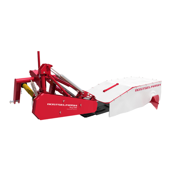
Place of name plate fitting is shown in Fig. 1.3. Fig. 1.3. Place of name plate fitting 1.4. General description of mower and its components 1.4.1. General description of mower Fig. 1.4. General view of mower ZTT-2,1... - Page 10 The mower (Fig. 1.4) is a hinged apparatus without worksite, it’s controlled and maintained by operator (tractor operator). Cutter bar 1 is a working element of mower, which is connected to bevel gear speed reducer by threaded coupling. Bevel gear speed reducer is fixed in plain bearing 19. Two floated cutting blades attached to each rotor mounted on mower cutter bar.
-
Page 11: Components Description
Blades cut herb on the principle of unsupported shear, pick up it and take out it from area of shear, moving over cutting bar. When striking the panel of outside divider the mowing herb is changing motion path, packing into the swath and standing down for tractor wheels run during successive pass. Swath width is set by swath former vanes motion. - Page 12 In this case mower controls are steering relatively swing mount 12 (Fig. 1) backward along the tractor movement, thus taking away cutter bar with reducer from obstruction, minimizing possibility of cutter bar and reducer elements damage. Tractional safety lock should activate under force of 3000 N (300 kg) applied to center part of cutter bar.
- Page 13 Fig. 1.7. Mower cutter bar It’s required to observe constantly for condition of mow out blades and grease in reducer 4 and cutter bar. Missing of grease can cause bar and reducer overheating and their malfunction. 1.5.4. Cutter bar balance unit Balance unit (Fig.
- Page 14 Fig. 1.9. Functional diagram of mower ZTT-2,1 Fig. 1.10. Functional diagram of mower ZTT-2,4...
- Page 15 Fig. 1.11. Functional diagram of mower ZTT-2,8 Functional diagram of mower ZTT-2,4 is given in Fig.10, mower TT-2,8 in Fig. 1.11. 1.5.6. Hydraulic system Mower hydraulic system (Fig. 1.12) is made as a single-line one and consists of a cylinder actuator A with throttle B, high pressure sleeve D with joint quick disconnect clutch C.
- Page 16 Fig. 1.12. Hydraulic system Fig. 1.13. Arrangement of plug for quick disconnect clutch and latch for cardan shaft fastening. 1.5.7. Specifications Mower specifications are given in Table 1.1. Table 1.1 Mower model Description ZTT-2,1 ZTT-2,4 ZTT-2,8 Type Hinged Output rate per 1 hour of main time, ha/h, up to Working width, m Mass without spares and package, max., kg 460±25...
-
Page 17: Safety Requirements
Dimensions, mm, max length 2370±50 2370 2160 width 3700±50 4000 4560 height 1150±50 1050 1400 Dimensions along with tractor МТЗ-80, mm, max. Operating position length 5920 6230 width 3740 4500 4700 height 2540 Stowage position 5080 5450 5390 length width 2700 2820 height... -
Page 18: Warning Plates
Moving of tractor with mower without setting and fixing of cutter device vertically (transport position); When testing, to start and operate mower, location of unauthorized people at distance less than 50 m from mower; replace blades without preliminary lock of rotors from turning; ... - Page 19 Table 2.1 Symbol Meaning of symbol Common attention! Switch off tractor ignition! Warning! Rotating parts! Maintenance! See Instructions!
- Page 20 Symbol Meaning of symbol Caution! PTO shaft speed of tractor is 540 r.p.m.! Warning! Danger of winding on cardan shaft! Caution! Hazard for hands! Caution! Hazard for feet! Warning! Staying of unauthorized persons is not allowed at distance less than 50 m !
- Page 21 Symbol Meaning of symbol Caution! Check rotors for attachment security! Safety precautions before start Don’t perform maintenance and repair works with tractor PTO Lifting point Clearance Lifting diagram...
- Page 22 Fig. 2.1. Places of warning symbol arrangement on mower models ZTT-2,1 and ZTT-2,4 Fig. 2.2. Warning plate arrangement on mower model ZTT-2,8...
-
Page 23: Preparation For Operation
3. Preparation for operation 3.1. Transportation The mower can be transported by rail, water and motor transport when delivering it to place of operation.. Method of loading, placing and fitment should be in compliance with standards and regulations specified for these modes of transport. The mower shall be delivered to Customer complete and assembled by single packing place (Fig. - Page 24 Fig. 3.2. Lifting diagram of mower model ZTT-2,8 During transportation, loading and unloading the mower should be fixed according to Fig. 3.3. Fig. 3.3. Fixing of mower during loading and unloading On vehicle the mower is fixed by motor strapping belts (strainers, straps, etc.). When moving in the farm unit the mower is transported along with tractor.
-
Page 25: Final Assembly
3.2. Final assembly When removing mower from vehicle, it shall be assembled finally. During final assembly it’s required to do the following: depreserve mower by removing grease from external preserved surfaces, cleaning them with rags moistened with solvents and then dry or wipe with rags dry. Keep rags with remains of solvent and grease in specially assigned place;... - Page 26 Fig. 3.3. Proper position of tractor hinge For mower model ZTT-2,8 If tractor equipped with limiter of hinge lifting with position indicator, then it’s required to set lower tractor hinge lever so that mower transmission shaft was at 750 mm height above the ground (Fig.
-
Page 27: Mower Connection To Tractor
3.5. Mower connection to tractor Mower hinging is undertaken by single operator (tractor operator). Connect lower axels of three point mower hinge to longitudinal rods of tractor hinge. Move tractor backward to mower and lower tractor hinge to lowermost position (485±25 mm). Connect tractor center rod to the top three point hinge axel and cotter it with quick-release pin. -
Page 28: Service And Adjustment Instructions
4. Service and adjustment instructions 4.1. Operation conditions The mower is ready for operation after its hinging on tractor, greasing, adjusted and run idle. When operating the mower observe the following rules: check specified parameters of procedure accomplishment: cutting height – with use of ruler, span width –... - Page 29 Check tightening of all bolts and nuts in every 15-20 min during first hour of mower operation. Fig. 4.1. Telescopic locking mechanism To move ZTT-2.8 mower into stowage position it’s required the following: raise cutting device by mower cylinder actuator till automatic latch 1 fastening (Fig. 4.2);...
- Page 30 Fig. 4.2. Moving of mower ZTT-2,8 to stowage position 4.1.2. Replacement of cutter bar blades Caution! To provide mower working elements operation reliability and safety blades, bolts, disks and nuts should be replaced with original parts only, specified in parts catalog. Blade replacement is carried out in case if: ...
- Page 31 mount original blades only; tightening torque of blade is М=95 Nm! Digital designation is coined on each blade. Replace blades according to Fig. 4.3, 4.4 , 4.5 and 4.6. Fig. 4.4. Attachment of cutting blade to rotor Fig. 4.5. ZTT-2,1 Diagram of cutting blades replacement in model Fig.
- Page 32 Fig. 4.7. Diagram of cutting blades replacement for model ZTT-2,8 Blade attachment bolt should be replaced in case if (Fig. 4.7): bolt is deformed; bolt is heavy worn from one side; diameter of blade seat is less than 15 mm (for model ZTT-2,8 – 18 mm). Blade attachment nut should be replaced in case if (Fig.
-
Page 33: Maintenance
Fig. 4.9. Marginal sizes for model ZTT-2,8 4.2. Maintenance 4.2.1 Balancing spring adjustment Balancing springs (Fig. 1.8) are designed to provide even pressure of cutter bar on the soil along the whole area of panel bottom and also for profiling of soil relief roughness. 4.2.2. -
Page 34: Maintenance
Q=210H (21 kg) Fig. 4.10. Adjustment of belt drive tension It should be noted that belt drive tension more than 15±1,5 mm can cause damage of belts and drive! Tension less than 15±1,5 mm can cause belt slippage in shafts that leads to poor mass mowing grass binding on cutter bar rotors. - Page 35 5.2.2. Procedures performed during preparation for storage When preparing mower for winter storage it’s required to do the following: perform operations according to shift maintenance; preserve movable and adjustable threaded surfaces; remove high pressure sleeve, blades, belts, tent from apparatus for storage in specially designed place;...
- Page 36 Number of Point greasing Intervals of Object Type of grease (Fig.5.1) points/volume, grease, h or analogs Small bar plain 1/0.07 bearing Oils used in tractor Hydraulic system continuously hydraulic system Transmission oil TAD-17И GOST Bevel gear speed 240 or once a 1/0.75 23652-79 or any reducer of cutter bar...
- Page 37 Fig. 5.1. Greasing objects Fig. 5.2. Cardan shaft greasing points...
- Page 38 Table 5.2. Symbol Interval, motohours every 10 every 60 For mower ZTT-2,8 perform greasing according to chymotological chart (Table 5.3). Table 5.3 Chymotological chart Number of Point Intervals of Object greasing Type of grease (Fig. 10) grease, h points/volume, kg Hinge plain bearing 1/0.01 Small bar plain bearings...
- Page 39 oil level is considered to be normal if level reaches lower hole edge (Fig. 5.4). Filler neck is located between rotor 1 and 2. Fig. 5.4. Checking of oil level in cutter bar of mowers ZTT-2,1, ZTT-2,4, ZTT-2,8 Perform oil changing after first 50 h of mower operation and then in every 100 h of operation. If apparatus operated less than 100 h a season, then oil should be changed during mower removal for storage.
-
Page 40: Storage
Trouble, external Probable reason Troubleshooting response Incorrect position of Adjust tractor hinge relative tractor hinge relative to to ground surface ground surface When running on foreign Appearing of sharp metal object cutting blade bent Shut down tractor PTO, stop noise downward and touches mower and replace blade cutter bar... -
Page 41: Apparatus Recycling
If required to store mower more than one year or at open site under the shed for more than two months and also post season of operation, perform the respective scheduled maintenance with mandatory operations on preservation, sealing and removal of separate components subject to warehouse storage. -
Page 42: Manufacturer's Warranty
9. Manufacturer’s warranty Manufacturer’s warranty: The Manufacturer guarantees the mower compliance to specifications requirements observe the User conditions on transportation, storage, mounting, usage and maintenance. Mower and its components warranty term is calculated since date of its sale by Manufacturer and is 24 months. - Page 43 Appendix 1 List of quick wearing parts Designation Description Qty, pcs/ Remarks apparatus 172.0107.41 (RASSPE) Blade Replacement with 1832533 (BELLON) allowed 172.0107.40 (RASSPE) Blade Replacement with 1832532 (BELLON) allowed 1832533 (BELLON) Blade Replacement with 172.0107.41 (RASSPE) is allowed 1832532 (BELLON) Blade Replacement with 172.0107.40 (RASSPE) is...
- Page 44 Appendix 2 List of spares for model ZTT-2.1 Description Description Qty, pcs Remarks /apparat. ZTT-00.740Б Tent 172.0107.41 (RASSPE) Blade Replacement with 1832533 (BELLON) is allowed 172.0107.40 (RASSPE) Blade Replacement with 1832532 (BELLON) is allowed 1832533 (BELLON) Blade Replacement with 172.0107.41 (RASSPE) is allowed 1832532 (BELLON) Blade...
- Page 45 Appendix 3 List of spares for model ZTT-2.4 Designation Description Qty, pcs Remarks /apparat. ZTT-00.750Б Tent 172.0107.41 (RASSPE) Blade Replacement with 1832533 (BELLON) is allowed 172.0107.40 (RASSPE) Blade Replacement with 1832532 (BELLON) is allowed 1832533 (BELLON) Blade Replacement with 172.0107.41 (RASSPE) is allowed 1832532 (BELLON) Blade...
- Page 46 Appendix 4 List of spares for model ZTT-2.8 Designation Description Qty, pcs Remarks /apparat. КРН-2.8.08.011Б Tent 172.0107.41 (RASSPE) Blade Replacement with 1832533 (BELLON) is allowed 172.0107.40 (RASSPE) Blade Replacement with 1832532 (BELLON) is allowed 1832533 (BELLON) Blade Replacement with 172.0107.41 (RASSPE) is allowed 1832532 (BELLON) Blade...
Need help?
Do you have a question about the Strige ZTT-2.1 and is the answer not in the manual?
Questions and answers