
Summary of Contents for Hensoldt Kelvin Hughes SBS-800 Series
- Page 1 SBS-800 SERIES SHORE BASED RADAR SYSTEMS OPERATOR & PLANNED MAINTENANCE HANDBOOK FIBRE SHARPEYE™ TRANSCEIVER SYSTEMS KH-1601-2 Issue 6...
- Page 2 No parts of this publication may be reproduced, transmitted, transcribed, translated or stored in any form or by any means without the written permission of HENSOLDT UK Limited. Where this document is translated or any translations that are included within this publication, the original English version of this document will remain the definitive document and should be referred to in any situation of doubt, confusion or conflict.
-
Page 3: Table Of Contents
SBS-800 Series Operator & Planned Maintenance Handbook Chapter 1: Contents Contents Contents ............................. 3 Health and Safety Warnings ..................... 5 English Health and Safety Warnings ..................5 Recommandations sanitaires et de sécurité ................. 11 Overview ..........................17 Unit Identification ........................17 Additional Documentation ..................... - Page 4 SBS-800 Series Operator & Planned Maintenance Handbook Chapter 1: Contents External Commands ......................59 Planned Maintenance ......................61 Overview and Safety Notices ....................61 Annual Maintenance ......................62 10-year Maintenance ......................69 Earth Bonding Maintenance ....................70 Contact Details ........................71 Abbreviations ..........................
-
Page 5: Health And Safety Warnings
SBS-800 Series Operator & Planned Maintenance Handbook Chapter 2: Health and Safety Warnings Health and Safety Warnings English Health and Safety Warnings FCC NOTICES IC RSS-GEN, Sec 8.4 Warning Statement- (Required for license-exempt devices) This device complies with Industry Canada license-exempt RSS standard(s). Operation is subject to the following two conditions: (1) this device may not cause interference, and (2) this device must accept any interference, including interference that may cause undesired operation of the device. - Page 6 SBS-800 Series Operator & Planned Maintenance Handbook Chapter 2: Health and Safety Warnings RADIATION HAZARDS WARNING: RADIATION HAZARD- NON-IONISING Avoid exposure to the main beam of a stationary radar antenna. Avoid standing closer than 2 metres from the central front face of the antenna. Users of cardiac pacemakers should be aware of the possibility that radio frequency transmissions can damage some devices or cause irregularities in their operation.
- Page 7 SBS-800 Series Operator & Planned Maintenance Handbook Chapter 2: Health and Safety Warnings WORKING ALOFT CAUTION: SAFETY ALOFT When working aloft or near any radar scanners, moving or RF radiating equipment, ALL power sources to the platform and equipment including Anti-Condensation Heater (ACH) supplies must be fully isolated. Prior to working aloft, all AC supply breakers to the system must be switched OFF and locked.
- Page 8 SBS-800 Series Operator & Planned Maintenance Handbook Chapter 2: Health and Safety Warnings ANTI-STATIC HANDLING HANDLING OF ELECTROSTATIC-SENSITIVE SEMICONDUCTOR DEVICES Certain semiconductor devices used in the equipment are liable to damage due to static voltage. Observe the following precautions when handling these devices in their un-terminated state, or sub-units containing these devices: Persons removing sub-units from equipment containing these devices must be earthed by a wrist strap and a resistor at the labelled point provided on/within the equipment.
- Page 9 SBS-800 Series Operator & Planned Maintenance Handbook Chapter 2: Health and Safety Warnings SOFTWARE LICENSING Only approved software may be used on Kelvin Hughes equipment. The use of unapproved or unlicensed software on any Kelvin Hughes equipment is strictly prohibited. The use of such software voids the warranty status of the unit. Any Kelvin Hughes designed software supplied whether pre-installed, supplied on CD/DVD or other removable media, is the copyright of Kelvin Hughes Ltd, which will not accept any responsibility for any damage or loss caused in whatever way by the use or misuse of the software.
- Page 10 SBS-800 Series Operator & Planned Maintenance Handbook Chapter 2: Health and Safety Warnings ANTENNA LIFTING Care should be taken when unpacking or lifting antennas to ensure that the waveguide is not bent, crushed or damaged during handling. Support the antenna near the ends when lifting it out of the packing and when fitting into position on the turning mechanism.
-
Page 11: Recommandations Sanitaires Et De Sécurité
AVERTISSEMENT Tous les équipements conçus par HENSOLDT sont construits de manière à ce que l'accès aux hautes tensions ne puisse être obtenu qu'après avoir utilisé un outil, comme une clé ou un tournevis. Les étiquettes d'avertissement sont bien en vue à la fois dans l'équipement et sur les capots de protection. - Page 12 La distance de sécurité de l'antenne pour tous les systèmes SBS-800 est proche du cercle de rotation de l'antenne, bien que HENSOLDT ne recommande à aucun personnel de se trouver à proximité d'une antenne rotative en raison non seulement de l'exposition aux RF mais aussi du risque élevé...
- Page 13 émetteurs-récepteurs et de l'inverseur d'antenne est coupée à l'aide de contacteurs. HENSOLDT recommande que les interrupteurs à clé mentionnés ci-dessus soient utilisés en conjonction avec l'interrupteur homme en l'air mais recommande également que les utilisateurs de radars effectuent une évaluation de la sécurité et une procédure d'atténuation des risques en termes de verrouillage avant d'approuver tout travail sur l'équipement.
- Page 14 Isoler complètement et déconnecter mécaniquement toutes les sources de courant alternatif avant de fixer les bracelets de protection ESD aux différents points du système. RoHS DÉCLARATION Pour plus de détails sur les RoHS déclarations, veuillez contacter HENSOLDT dont les coordonnées se trouvent à la fin de ce manuel. L'ÉLIMINATION EN FIN DE VIE Lorsque l'équipement décrit dans le présent manuel a atteint la fin de sa durée de vie utile, les différentes pièces qui le composent...
- Page 15 équipement HENSOLDT est strictement interdite. L'utilisation d'un tel logiciel annule le statut de garantie de l'appareil. Tout logiciel conçu par HENSOLDT, qu'il soit préinstallé, fourni sur CD/DVD ou tout autre support amovible, est protégé par les droits d'auteur de HENSOLDT, qui n'acceptera aucune responsabilité pour tout dommage ou perte causé de quelque manière que ce soit par l'utilisation ou la mauvaise utilisation du logiciel.
- Page 16 SBS-800 Series Operator & Planned Maintenance Handbook Chapter 2: Health and Safety Warnings LEVAGE D'ANTENNE Lors du déballage ou du levage des antennes, il convient de veiller à ce que le guide d'ondes ne soit pas plié, écrasé ou endommagé...
-
Page 17: Overview
SBS-800 Series Operator & Planned Maintenance Handbook Chapter 3: Overview Overview Unit Identification This handbook details SBS-800 SharpEye™ systems comprising of Fibre S-Band and Fibre GaN X-Band transceivers X or S-Band low profile antenna LPA-A37 all variants LPA-A55 all variants LPA-A3 all variants Part &... -
Page 18: Analogue & Gaas Sharpeye™ Systems
SBS-800 Series Operator & Planned Maintenance Handbook Chapter 3: Overview Analogue & GaAs SharpEye™ Systems This handbook details SBS-800 SharpEye™ system comprising of S-Band Fibre and X-Band GaN transceivers Earlier SBS-800 systems were fitted with GaAs and analogue SharpEye™ transmission systems which carry different part numbers. - Page 19 SBS-800 Series Operator & Planned Maintenance Handbook Chapter 3: Overview Page intentionally blank KH-1601-2 Issue 6 Page 19 of 80...
-
Page 20: Typical Systems
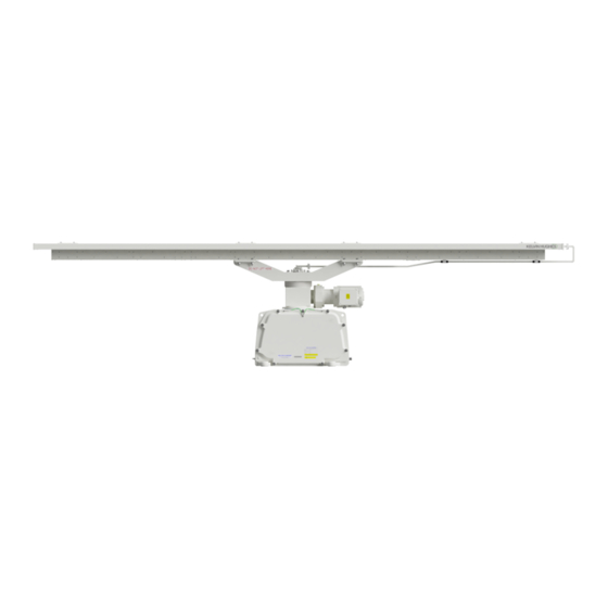
SBS-800 Series Operator & Planned Maintenance Handbook Chapter 3: Overview Typical Systems 3.5.1 SBS-800-1/SBS-800-2 KH-1601-2 Issue 6 Page 20 of 80... - Page 21 SBS-800 Series Operator & Planned Maintenance Handbook Chapter 3: Overview SBS-800-1 X-Band Doppler SharpEyeTM with 3.7m low profile antenna The SBS-800-1 system comprises of an X Band SharpEye Transceiver/Turning Mechanism incorporating Solid State radar transceiver utilising enhanced Digital Pulse Compression and Pulse Doppler Processing with Kelvin Hughes 3.7m (12ft) Low Profile Antenna (LPA).
- Page 22 SBS-800 Series Operator & Planned Maintenance Handbook Chapter 3: Overview SBS-800-2 X-Band Doppler SharpEye with 5.5m low profile antenna The SBS-800-2 system comprises of an X Band SharpEye Transceiver/Turning Mechanism incorporating Solid State radar transceiver utilising Enhanced Digital Pulse Compression and Pulse Doppler Processing with Kelvin Hughes 5.5m (18ft) Low Profile Antenna (LPA).
-
Page 23: Sbs-800-3
SBS-800 Series Operator & Planned Maintenance Handbook Chapter 3: Overview 3.5.2 SBS-800-3 KH-1601-2 Issue 6 Page 23 of 80... - Page 24 SBS-800 Series Operator & Planned Maintenance Handbook Chapter 3: Overview SBS-800-3 X-Band Doppler & frequency diversity SharpEye with 5.5m low profile antenna The SBS-800-3 system comprises of an X Band SharpEye Transceiver/Turning Mechanism incorporating Solid State radar transceiver utilising Enhanced Digital Pulse Compression, Pulse Doppler Processing and Frequency Diversity with Kelvin Hughes 5.5m (18ft) Low Profile Antenna (LPA).
-
Page 25: Sbs-800-51
SBS-800 Series Operator & Planned Maintenance Handbook Chapter 3: Overview 3.5.3 SBS-800-51 KH-1601-2 Issue 6 Page 25 of 80... - Page 26 SBS-800 Series Operator & Planned Maintenance Handbook Chapter 3: Overview SBS-800-51 S-Band Doppler SharpEye with 3.9m low profile antenna The SBS-800-51 system comprises of an S-Band SharpEye Transceiver/Turning Mechanism enclosure incorporating Solid State radar transceiver utilising Enhanced Digital Pulse Compression and Pulse Doppler Processing with Kelvin Hughes 3.9m (12.8ft) Low Profile Antenna (LPA).
-
Page 27: Switch On, Off & Emergency Stop
SBS-800 Series Operator & Planned Maintenance Handbook Chapter 4: Switch ON, OFF & Emergency Stop Switch ON, OFF & Emergency Stop ANTENNA ROTATION WARNING WARNING ANTENNA ROTATION SAFETY NOTICE When antenna motor power is connected to the system and switched ON, the antenna will rotate immediately regardless of the RUN command status (see conditions below). -
Page 28: Switch On
SBS-800 Series Operator & Planned Maintenance Handbook Chapter 4: Switch ON, OFF & Emergency Stop Switch ON FIRST TIME SWITCH ON Ensure the setting to work of the system has been successfully completed and signed off. POWER Check that all sources of external AC power are available and are switched ON. ANTENNA Ensure the antenna is clear of all obstructions and that it is safe to rotate. -
Page 29: Switch Off
SBS-800 Series Operator & Planned Maintenance Handbook Chapter 4: Switch ON, OFF & Emergency Stop Switch OFF SWITCH OFF The following describes how to switch OFF the SBS-800 system for operational purposes. The following does not include the switch OFF/shut down procedures for the track extractor, optional service display or external equipment attached to the system. -
Page 30: Emergency Antenna Stop
SBS-800 Series Operator & Planned Maintenance Handbook Chapter 4: Switch ON, OFF & Emergency Stop EMERGENCY ANTENNA STOP In an emergency, antenna rotation and system transmission can be stopped using ANY of the following mechanisms. RDU keyswitch: Place the Antenna Rotation keyswitch on the front of the Radar Distribution Unit into the OFF position. -
Page 31: System Isolation
SBS-800 Series Operator & Planned Maintenance Handbook Chapter 4: Switch ON, OFF & Emergency Stop System Isolation In addition to the normal health and safety requirements, the system must be made safe prior to carrying out any maintenance task by fully isolating and locking OFF all AC power including any UPS supported supplies to the system and where connected the Anti-Condensation Heater (ACH) supply as shown below: Place the Antenna Rotation keyswitch on the front of... - Page 32 SBS-800 Series Operator & Planned Maintenance Handbook Chapter 4: Switch ON, OFF & Emergency Stop Page intentionally blank KH-1601-2 Issue 6 Page 32 of 80...
-
Page 33: Anti-Condensation Heater (Ach)
SBS-800 Series Operator & Planned Maintenance Handbook Chapter 5: Anti-Condensation Heater (ACH) Anti-Condensation Heater (ACH) CONNECTION The Anti-Condensation Heater is not connected as standard. The ACH should only be connected where the SBS-800 system is to be switched OFF and left in an un-powered state when high humidity levels are anticipated. - Page 34 SBS-800 Series Operator & Planned Maintenance Handbook Chapter 5: Anti-Condensation Heater (ACH) Page intentionally blank KH-1601-2 Issue 6 Page 34 of 80...
-
Page 35: Operation Overview
SBS-800 Series Operator & Planned Maintenance Handbook Chapter 6: Operation Overview Operation Overview Local/Remote Control States Instructions on operating the system in Local and Remote control are detailed in the following sections: Local Control: See Section 7 Remote Control: See Section 8 ... -
Page 36: Switching From Local To Remote Control
SBS-800 Series Operator & Planned Maintenance Handbook Chapter 6: Operation Overview Switching from Local to Remote Control When Local control is no longer required, the Remote Control Local Control system MUST be switched to Remote. i.e. command & i.e. RDU front display or track Panel or optional extractor... -
Page 37: Transceiver Operational States
SBS-800 Series Operator & Planned Maintenance Handbook Chapter 6: Operation Overview Transceiver Operational States The following table shows the various operation states of the X or S-Band SharpEye™ transceivers within the gearbox/turning unit: Operation state Description Power is not applied to the transceiver and it is switched OFF. When power is applied to the system, the SharpEye™... -
Page 38: Performance Monitoring
SBS-800 Series Operator & Planned Maintenance Handbook Chapter 6: Operation Overview Performance Monitoring There are no user activated performance monitoring checks in the system. The SharpEye™ transceiver continuously runs background performance checks on forward power, reverse power, receiver sensitivity and temperature. If any of these parameters falls outside predetermined levels a warning message is sent to the Radar Distribution Unit indicating the nature of the fault. -
Page 39: Local Control
SBS-800 Series Operator & Planned Maintenance Handbook Chapter 7: Local Control Local Control Local Control Overview 7.1.1 RDU Local Controls A backlit LCD display shows the system LCD display status, menus, error and alarm messages No power, the RDU is not switched ON The power is switched ON and the Green system is being controlled locally or... -
Page 40: Remote/Local Switch
SBS-800 Series Operator & Planned Maintenance Handbook Chapter 7: Local Control 7.1.2 Remote/Local Switch A switch on the front of the Radar Distribution Unit allows the selection of Remote or Local operation. The following explains the basic operation of the system in these two modes. WARNING ANTENNA ROTATION Depending on the position of the safety switches, the antenna will rotate regardless of the position of... -
Page 41: Lcd Panel Operation
SBS-800 Series Operator & Planned Maintenance Handbook Chapter 7: Local Control 7.1.3 LCD Panel Operation The LCD display on the front of the RDU is a backlit, two line 16 character display. Push buttons located either side of the display allow the control of the setup menus, local control and status monitoring. -
Page 42: Alarms
SBS-800 Series Operator & Planned Maintenance Handbook Chapter 7: Local Control 7.1.5 Alarms When the system is in local control Note and an alarm condition exists, the lower right button will flash red and an audible alarm will be generated. VIEW ALARM CONDITION: To view the alarm message/condition, select the status menu and the alarm condition(s) will be displayed in the lower section of the LCD... -
Page 43: Menus
SBS-800 Series Operator & Planned Maintenance Handbook Chapter 7: Local Control Menus There are four menus that can be selected from the LCD display; the menus vary depending on system settings. Each menu is detailed in the following sections: Menu availability Menu Description Local... - Page 44 SBS-800 Series Operator & Planned Maintenance Handbook Chapter 7: Local Control Page intentionally blank KH-1601-2 Issue 6 Page 44 of 80...
-
Page 45: Menus Overview
SBS-800 Series Operator & Planned Maintenance Handbook Chapter 7: Local Control 7.2.2 Menus Overview KH-1601-2 Issue 6 Page 45 of 80... -
Page 46: Status Menu
SBS-800 Series Operator & Planned Maintenance Handbook Chapter 7: Local Control 7.2.3 STATUS Menu The STATUS MENU on the Radar Distribution Unit is used by the operator or the system maintainer to view but not configure or adjust the current system settings. The Status menu is available on the RDU in both the REMOTE and LOCAL setting. - Page 47 SBS-800 Series Operator & Planned Maintenance Handbook Chapter 7: Local Control 7.2.3.2 Radar Control Status Status Menu Radar Comms MISM Software Status Control SharpEye Network Exit Status status status Info Status By scrolling through the radar control status menus, the following system configurations and settings can be viewed but not adjusted.
- Page 48 SBS-800 Series Operator & Planned Maintenance Handbook Chapter 7: Local Control 7.2.3.3 SharpEye Status Menu Radar Comms MISM Software Status Control SharpEye Network Exit Status status status Info Status By scrolling through the SharpEye menus, the following system conditions can be viewed but cannot be adjusted.
- Page 49 SBS-800 Series Operator & Planned Maintenance Handbook Chapter 7: Local Control SharpEye Number of hours the SharpEye has been Status 5: Times ON Time (continued) switched ON (HH:MM) Number of hours the system has been Run-time transmitting (HH:MM) The current temperature of FPGA 1 (°C) in the Status 8: Temp ...
- Page 50 SBS-800 Series Operator & Planned Maintenance Handbook Chapter 7: Local Control 7.2.3.5 NTP Time Status Menu Radar Comms MISM Software Status Control SharpEye Network Exit Status status status Info Status The configuration of the NTP time status can be viewed but not adjusted. Time Stamp ON/OFF Displays the NTP server IP address set during the commissioning of the...
- Page 51 SBS-800 Series Operator & Planned Maintenance Handbook Chapter 7: Local Control 7.2.3.7 MISM Status Status Menu Radar Comms MISM Software Status Control Network Exit SharpEye status Info Status status Status By scrolling through the MISM status (Modular Interface System Module) menus, the status of each of the 12 slots on the backplane can be viewed.
- Page 52 SBS-800 Series Operator & Planned Maintenance Handbook Chapter 7: Local Control 7.2.3.8 Software Info Status Menu Radar Comms MISM Software Status Control SharpEye Network Exit Info Status status status Status By scrolling through the software info menus, the various software versions for the system can be identified: MISB backplane Software identification number for the backplane (e.g.
-
Page 53: Control Menu
SBS-800 Series Operator & Planned Maintenance Handbook Chapter 7: Local Control 7.2.4 CONTROL Menu When operating in Local mode, the CONTROL MENU on the Radar Distribution Unit is used by the maintainer to adjust the system settings. MENU AVAILABILITY The control menu is only available on the RDU when the Remote/Local switch is set to Local and the service display is off-line, is not connected or is switched OFF. - Page 54 SBS-800 Series Operator & Planned Maintenance Handbook Chapter 7: Local Control 7.2.4.2 TX Power Control Menu Range Int. Tx Freq. Mute Rain Sweep Exit Power Mode Rejection The output power of the SharpEye transceiver can be switched between High (default) and Low. High power: The SharpEye transceiver transmits at full power;...
- Page 55 SBS-800 Series Operator & Planned Maintenance Handbook Chapter 7: Local Control 7.2.4.4 Mute Control Menu Range Int. Mute Tx Freq. Rain Sweep Exit Mode Power Rejection The Mute function allows a 360° transmission inhibit to be Enabled/Disabled. Mute ON: Transmission is muted/stopped i.e.
- Page 56 SBS-800 Series Operator & Planned Maintenance Handbook Chapter 7: Local Control 7.2.4.6 Int. Rejection Control Menu Range Int. Tx Freq. Mute Rain Sweep Exit Mode Power Rejection THIS MENU IS NOT ENABLED IN SBS-800 SYSTEMS. This menu is not enabled as the system uses Doppler principles automatically. This menu will have no function in this system.
-
Page 57: Setup/Default Menus
SBS-800 Series Operator & Planned Maintenance Handbook Chapter 7: Local Control 7.2.4.8 Control Menu Range Int. Tx Freq. Mute Rain Sweep Exit Mode Power Rejection The RPM function allows the operator to stop rotation (OFF), select Auto or one of three pre-defined Note 1 antenna rotation speeds. - Page 58 SBS-800 Series Operator & Planned Maintenance Handbook Chapter 7: Local Control Page intentionally blank KH-1601-2 Issue 6 Page 58 of 80...
-
Page 59: Remote Control
SBS-800 Series Operator & Planned Maintenance Handbook Chapter 8: Remote Control Remote Control When the Radar Distribution Unit is set to Remote operation, the external command and display system or track extractor has control of the system. For test purposes, the optional service display can be configured for Remote control and be connected to the track extractor (TE) port to test the serial port functionality. - Page 60 SBS-800 Series Operator & Planned Maintenance Handbook Chapter 8: Remote Control Page intentionally blank KH-1601-2 Issue 6 Page 60 of 80...
-
Page 61: Planned Maintenance
SBS-800 Series Operator & Planned Maintenance Handbook Chapter 9: Planned Maintenance Planned Maintenance Overview and Safety Notices This section provides information on the planned maintenance for all standard systems within the SBS-800 range. MAINTENANCE RECORD The following pages have been designed to be printed, completed and stored as a maintenance record for standard systems. -
Page 62: Annual Maintenance
SBS-800 Series Operator & Planned Maintenance Handbook Chapter 9: Planned Maintenance Annual Maintenance EQUIPMENT DETAILS Transceiver/gearbox Low profile antenna Part number: DTX-A Part number: LPA-A Serial number: Serial number: MOD strike MOD strike Radar Distribution Unit (RDU) Man Aloft Switch (MAS) SBS-A132 ☐... - Page 63 SBS-800 Series Operator & Planned Maintenance Handbook Chapter 9: Planned Maintenance STANDARD ANTENNA SUB-SYSTEM INSPECTION Task Description Pass Fail Clean the antenna facia with a soft cloth moistened in a mild non- abrasive soap solution. ☐ ☐ Cleaning Note : Cleaning the antenna is important as the system performance can be degraded if the antenna transmission face becomes obscured by dirt.
- Page 64 SBS-800 Series Operator & Planned Maintenance Handbook Chapter 9: Planned Maintenance TRANSCEIVER/GEARBOX INSPECTION Task Description Pass Fail General Clean all exterior surfaces with a soft cloth moistened in a mild non- ☐ ☐ cleaning abrasive soap solution. Ensure that all securing bolts for the transceiver/gearbox and antenna are secure and show no signs of severe corrosion or ☐...
- Page 65 SBS-800 Series Operator & Planned Maintenance Handbook Chapter 9: Planned Maintenance RADAR DISTRIBUTION UNIT (RDU) Task Description Pass Fail External Clean with a soft, non-abrasive cloth lightly moistened ☐ ☐ surfaces in a mild soap solution. Cleaning Open the door of the Radar Distribution Unit using a Internal ☐...
- Page 66 SBS-800 Series Operator & Planned Maintenance Handbook Chapter 9: Planned Maintenance VF-nC3 Single Phase Inverter (SBS-A229): Checking the fan run-time - On the static inverter control panel, open the small access door, press the MODE button twice and ensure that Fr-F is displayed - Rotate the thumb wheel until FE14 is displayed then press the thumbwheel to access the fan menu.
- Page 67 SBS-800 Series Operator & Planned Maintenance Handbook Chapter 9: Planned Maintenance MAN ALOFT SWITCH Task Description Pass Fail Physical Ensure that all fastenings are secure and show no signs of severe ☐ ☐ inspection corrosion or damage. Switch Ensure the switch operation is smooth and that both the Free and ☐...
- Page 68 SBS-800 Series Operator & Planned Maintenance Handbook Chapter 9: Planned Maintenance SAFETY SWITCH TESTS SYSTEM CONFIGURATION The following tests should be carried out with power restored to the system and the transceiver placed into RUN. WARNING: When carrying out the following test, do not contravene any health and safety precautions regarding working aloft, antenna or electrical safety.
-
Page 69: 10-Year Maintenance
SBS-800 Series Operator & Planned Maintenance Handbook Chapter 9: Planned Maintenance 10-year Maintenance CHANGING THE STATIC INVERTER IN THE RDU In addition to the annual maintenance requirements indicated earlier in this section, after 10-years of use, the static inverter located within the Radar Distribution Unit must be changed as over time, the electrolytic capacitors within the inverter can dry out. -
Page 70: Earth Bonding Maintenance
SBS-800 Series Operator & Planned Maintenance Handbook Chapter 9: Planned Maintenance Earth Bonding Maintenance Where an earth/chassis bonding point has been found to be corroded or fails a conductivity test, the bonding joint should be dismantled, cleaned and reassembled as follows: CAUTION ISOLATE THE SYSTEM BEFORE COMMENCING THIS TASK. -
Page 71: Contact Details
SBS-800 Series Operator & Planned Maintenance Handbook Chapter 10: Contact Details 10 Contact Details Kelvin Hughes Ltd Voltage 6 Mollison Avenue Enfield EN3 7XQ UNITED KINGDOM Phone: +44 (0)1992 805 200 +44 (0) 1992 805 310 email surveillance.support@kelvinhughes.co.uk Service Phone +44 (0)1992 805 200 email surveillance.tech@kelvinhughes.co.uk... - Page 72 SBS-800 Series Operator & Planned Maintenance Handbook Chapter 10: Contact Details Page intentionally blank KH-1601-2 Issue 6 Page 72 of 80...
-
Page 73: Abbreviations
SBS-800 Series Operator & Planned Maintenance Handbook Chapter 11: Abbreviations 11 Abbreviations The following abbreviations are used in Kelvin Hughes publications. Some may not appear in this handbook and are shown for reference only. Alternating Current Electronic Plotting Aid Anti-condensation heater EPFS External Position Fixing System Azimuth Clock Pulse (azimuth pulses) - Page 74 SBS-800 Series Operator & Planned Maintenance Handbook Chapter 11: Abbreviations Navigation SOLAS Safety Of Life At Sea Short Pulse Nautical Mile Speed Not More Than STAB Stability NORM Normal STBY Standby N-UP North-UP Sensitivity Time Control Officer On Watch Speed to Go Own Ship Speed Through Water Personal Computer...
-
Page 75: Index
SBS-800 Series Operator & Planned Maintenance Handbook Chapter 12: Index 12 Index French ......11 Switch ....... 40 Residual voltages ....5 RoHS........ 8, 14 AC supply isolation ....31 RPM menu ......57 Adverse weather - Checks Interference rejection menu ..56 after... - Page 76 SBS-800 Series Operator & Planned Maintenance Handbook Chapter 12: Index Page intentionally blank KH-1601-2 Issue 6 Page 76 of 80...
- Page 77 SBS-800 Series Operator & Planned Maintenance Handbook Chapter 12: Index NOTES (Page 1 of 2) KH-1601-2 Issue 6 Page 77 of 80...
- Page 78 SBS-800 Series Operator & Planned Maintenance Handbook Chapter 12: Index NOTES (Page 2 of 2) KH-1601-2 Issue 6 Page 78 of 80...
- Page 79 SBS-800 Series Operator & Planned Maintenance Handbook Chapter 12: Index Page intentionally blank KH-1601-2 Issue 6 Page 79 of 80...
- Page 80 Kelvin Hughes Limited Registered Office: Voltage, 6 Mollison Avenue, Enfield EN3 7XQ, UK. Incorporated in England No. 01030135...
Need help?
Do you have a question about the Kelvin Hughes SBS-800 Series and is the answer not in the manual?
Questions and answers