
Summary of Contents for Insight Control ZONE-IT
- Page 1 Model: C-ZONE-IT Installation Manual www.insightcontrol.net.au 1300 665 831 Insight Control ZONE-IT Installation Manual...
- Page 2 If further information is required by the purchaser regarding an installation, application, or maintenance activity, please contact an Insight Control representative or the installing contractor. SAVE THIS MANUAL FOR FUTURE REFERENCE...
-
Page 3: Table Of Contents
About ................................. 4 ZONE-IT Controller ............................4 Control Usage ..............................4 Touchpad ............................... 4 System overview ..............................5 System components ............................5 Operating Instructions ........................... 5 Typical system installation..........................6 Technical notes .............................. 6 Motorised Dampers ............................6 Cabling Requirements ........................... 6 Component Positioning .......................... -
Page 4: About
Restricts the damper from fully closing to maintain a minimum airflow. Control Usage ZONE-IT is a variable air volume zone controller suitable for use with any centralised conditioning source (e.g. reverse cycle systems) Zoning kits comprise of one of each of the following components. -
Page 5: System Overview
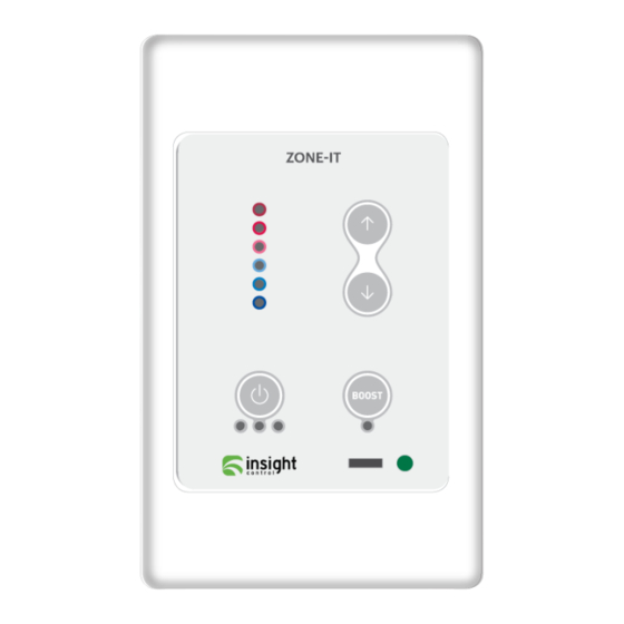
System components 1. TFORM-24 - 24volt Transformer 2. C-ZONE-IT – ZONE-IT controller 3. MDB-XXX-IC – Motorised Damper barrel, where XXX is the size in millimetres Operating Instructions Press the button to turn the zone On and Off. If the green LED below the button is lit, then the zone is ON. -
Page 6: Typical System Installation
Motorised Dampers Motorised dampers connect to the touchpad via the zone output socket on the back. The ZONE-IT version is suitable for use with MDB-XXX-IC 4Nm motorised dampers only. The motorised dampers may be connected in parallel with a maximum of two motors per zone output. -
Page 7: Connection Diagram
EXT position when utilising optional external room sensor. The following table lists some commonly reported fault conditions and suggested corrective action. Further assistance may be obtained from Insight Control support on 1300 665 831 if needed. Symptom Suggested remedial action Red Fault LED is lit on motor Excess current draw on output. -
Page 8: Innocab Cable Crimping Instructions
5. Squeeze the handles firmly (see important note above) to set the contacts and secure the cable, thus completing the operation. 6. Repeat the same procedure for each cable termination. Insight Control ZONE-IT Installation Manual... -
Page 9: Specifications
Electrical Requirements Power input to ZONE-IT 24 VAC ± 10% Line frequency 50 Hz Environmental Requirements Operating temperature 0°C to 50°C Altitude 0 to 2000m Operating relative humidity 10% to 80% Positioning Avoid static electricity hazards Avoid electromagnetic radiation sources... - Page 10 Phone: 1300 665 831 Email: sales@insightcontrol.net.au Website: www.insightcontrol.net.au Address: D3 / 5 Grevillea Place Brisbane Airport QLD 4008 Insight Control ZONE-IT Installation Manual...
Need help?
Do you have a question about the ZONE-IT and is the answer not in the manual?
Questions and answers