Advertisement
Quick Links
Kahlenberg Instruction Sheet 323
INSTALLATION, OPERATION, AND MAINTENANCE
1)
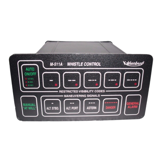
GENERAL - The function of the Whistle Control is to provide convenient operation of
sound signaling device from a single control panel for At-Will, Restricted Visibility, and
Maneuvering signaling as required. The M-511C also generates the SOLAS General Alarm
Signal, or may be integrated with another alarm system on board which generates this signal.
2)
DESCRIPTION - The M-511C is a compact solid state electronic Whistle Control
within a watertight powder coat finished aluminum enclosure. It is operated from a flush
mounted membrane switch keypad with embossed keys.
3)
OPERATION -
• CURRENT REQUIREMENT OF M-511C: .25 Amps
• SWITCHING CAPACITY OF M-511C: 1.75 Amps Maximum
• D.C. VOLTAGE REQUIREMENT: 12 TO 24 VOLT D.C.
• A.C. VOLTAGE REQUIREMENT: 100-240 VOLT A.C.
CAUTION: THE M-511C IS FUSE PROTECTED, HOWEVER, BE CERTAIN NOT
TO EXCEED THE 1.75 AMP MAXIMUM SWITCHING CAPACITY. THIS CAN
OCCUR IF MULTIPLE DEVICES ARE CONNECTED SUCH AS ADDITIONAL
LIGHTS OR SOUND PRODUCING DEVICES. A SUITABLE RELAY MUST BE
INSTALLED FOR CONTROLLING THESE DEVICES.
The M-511C A.C. Whistle Control circuit board is powered by 12 or 24 DC voltages with a
current requirement of .25 amps (maximum) and a switching capacity of 1.75 amps (maximum).
This unit also includes a power supply circuit board that accepts 100-240 Volt A.C. 50/60 Hz
power. The A.C. connections are made within the additional galvanized electrical box added to
the back of the unit. Both the A.C. and D.C. inputs of the timer may be connected
simultaneously. In this way, in case of A.C. power loss, the M-511C will continue to operate on
D.C. backup power.
The M-511C is designed to activate a solenoid valve or similar horn-activating device operating
on the same voltage as the M-511C. Activation of the horn can be accomplished several ways
depending upon the type of signal desired. For "At-Will" operations use the "Manual/At-Will"
button, this button will signal the device instantly at all times regardless of the mode of
operation. There are five (5) predetermined Restricted Visibility codes within the M-511C and
they are indicated on the associated button of the keypad. For a definition of these codes and
their uses, refer to the reference sheet included with these instructions. Pressing the "Auto
On/Off" button activates the five code buttons. Upon activation of the Automatic mode, the red
LED light of the activated code will light and signaling of the device for that code will
commence after a 10 second delay. This designed delay is to prevent commencement of the
M-511C A.C. WHISTLE CONTROL
Rev. 6/29/2011, Page 1 of 7
Advertisement

Summary of Contents for Kahlenberg M-511C
- Page 1 LIGHTS OR SOUND PRODUCING DEVICES. A SUITABLE RELAY MUST BE INSTALLED FOR CONTROLLING THESE DEVICES. The M-511C A.C. Whistle Control circuit board is powered by 12 or 24 DC voltages with a current requirement of .25 amps (maximum) and a switching capacity of 1.75 amps (maximum).
-
Page 2: Installation
Auto mode (if on). The M-511C is designed to be used as a single unit or in conjunction with other M-511C units, and with multiple remote “At-Will” buttons, such as the Kahlenberg M-131A, M-126, or any customer supplied two contact button. - Page 3 However if any parts listed on the attached Parts List drawings are required for any reason, please refer to the associated part number when ordering. If the M-511C should fail to operate properly please contact Kahlenberg Brothers Company for recommended action or return to Kahlenberg for prompt analysis and repair.
- Page 4 Kahlenberg Instruction Sheet 323 Rev. 6/29/2011, Page 4 of 7 RESTRICTED VISIBILITY CODES RULE 35 INTERNATIONAL & INLAND IN OR NEAR AN AREA OF RESTRICTED VISIBILITY, WHETHER BY DAY OR NIGHT, THE SIGNALS PRESCRIBED IN THIS RULE ARE AS FOLLOWS:...
- Page 5 Kahlenberg Instruction Sheet 323 Rev. 6/29/2011, Page 5 of 7 MANEUVERING CODES RULE 34 INTERNATIONAL - RULE (A) WHEN VESSELS ARE IN SIGHT OF ONE ANOTHER, A POWER-DRIVEN VESSEL UNDERWAY, WHEN MANEUVERING AS AUTHORIZED OR REQUIRED BY THESE RULES, SHALL INDICATE THAT MANEUVER BY THE FOLLOWING SIGNALS ON...
- Page 6 Kahlenberg Instruction Sheet 323 Rev. 6/29/2011, Page 6 of 7 INLAND - RULE (A) WHEN POWER-DRIVEN VESSELS ARE IN SIGHT OF ONE ANOTHER AND MEETING OR CROSSING AT A DISTANCE WITHIN HALF A MILE OF EACH OTHER, EACH VESSEL UNDERWAY, WHEN MANEUVERING AS AUTHORIZED OR REQUIRED BY...
- Page 7 Kahlenberg Instruction Sheet 323 Rev. 6/29/2011, Page 7 of 7 INLAND - RULE (C) WHEN IN SIGHT OF ONE ANOTHER (I) A POWER DRIVEN VESSEL INTENDING TO OVERTAKE ANOTHER POWER DRIVEN VESSEL SHALL INDICATE HER INTENTION BY THE FOLLOWING SIGNALS ON HER WHISTLE:...
- Page 12 Wiring Conversion from M-511 to M-511A D.C. Versions M-511 M-511A (+) in Terminal 5 (-) in Terminal 3 Terminal 2 Terminal 3 Terminal 2 A.C Version M-511 M-511A Black Black White Brown Orange Green (Ground) Red (Disregard)
- Page 13 AT THIS JUMPER THERE ARE 3 PINS. JUMPER IS PLACED OVER TWO PINS ON THE RIGHT AS SHIPPED FROM FACTORY.
Need help?
Do you have a question about the M-511C and is the answer not in the manual?
Questions and answers