
Related Manuals for Xaar XJ128 Series

Summary of Contents for Xaar XJ128 Series
- Page 1 XJ128 High Performance Ink Jet Printhead XJ128/200 XJ128/200 Plus XJ128/360 Guide to Operation XJ128 Guide to Operation Xaar Document no D031010302 Version A Xaar Confidential...
- Page 2 XJ128 and XJ128 Plus Printhead XAAR XJ128 Guide to Operation _______________________________ Xaar Science Park Cambridge CB4 OXR United Kingdom Phone +44 (0) 1223 423663, Fax +44 (0) 1223 423590 XJ128 Guide to Operation Xaar Document no: D031010302 Version A Page 1...
-
Page 3: Table Of Contents
Serial number ......................12 Product specifications ...................... 13 3.2.1 Printhead life........................ 14 4 Mechanical Guide............15 Channel numbering and side definition................15 Printhead mounting ......................16 4.2.1 Printhead orientation ....................16 XJ128 Guide to Operation Xaar Document no: D031010302 Version A Page 2... - Page 4 Providing a negative pressure ink supply................. 38 7.3.1 Gravity fed negative pressure ink supply..............38 7.3.2 Vacuum fed negative pressure ink supply..............39 Ink supply system design ....................39 XJ128 Guide to Operation Xaar Document no: D031010302 Version A Page 3...
- Page 5 Printing angle and horizontal / vertical resolution ratios ........56 9.2.8.2 Extraction of image data..................57 10 Trouble Shooting ............59 10.1 Printhead problems ......................59 10.2 Returning printhead(s) to Xaar..................59 XJ128 Guide to Operation Xaar Document no: D031010302 Version A Page 4...
- Page 6 Safety standards ........................63 CE Compliance and working environment ................64 Appendix D, Mechanical drawing ....................65 Appendix E, The Xaar flex-cable ....................66 Glossary ................67 Index ................68 XJ128 Guide to Operation Xaar Document no: D031010302 Version A Page 5...
-
Page 7: Introduction
XJ128 and XJ128 Plus Printhead Introduction 1.1 Overview This document is only valid for the Xaar XJ128 product. This document is provided to supply details and information relating to the XJ128 printhead and it’s operation. The document will cover the following sections: ... -
Page 8: Safety Instructions
XJ128 and XJ128 Plus Printhead 1.2 Safety instructions Although all efforts have been made to ensure that the XJ128 is safe for use, Xaar cannot be held responsible for any incidents or injuries resulting from mishandling or misuse. It is important to ensure that liquid does not come into contact with electrical areas and that appropriate safety precautions are taken when using the XJ128 printhead. -
Page 9: General Product Information
PZT block. An electrode is then placed onto the sides of the channel walls allowing a voltage to be applied across it. The way in which Xaar makes the wall bend due to the applied voltage is known as “shear mode.” Two channels share the wall, and hence the term “shared wall.”... -
Page 10: Product Handling And Installation
Xaar printheads are static sensitive devices, which can be damaged if they are touched without the necessary precautions being taken. Xaar printheads are supplied in antistatic packaging. These should only be opened and handled in an anti-static or electrostatic protected area (EPA). Unpacking and handling of the printheads should be performed with the correct electrostatic discharge (ESD) precautions such as a grounded wrist strap and conductive work mat. -
Page 11: Hot-Plugging
Should a printhead be removed from an application, the printhead should be flushed clean of ink with the appropriate Xaar cleaning solution. The cleaning solution should then be purged out of the printhead with clean, dry filtered air. This process is detailed in the Ink and Printhead User Guide documentation. -
Page 12: Product Support
XJ128 and XJ128 Plus Printhead 2.5 Product support Support for all Xaar products is available from Xaar. Please contact your regional office for further information. Please refer to section 11 for details. Product Description The product description detailed in the next section provides a brief overview of the main components that make up the XJ128 printhead. -
Page 13: Cover
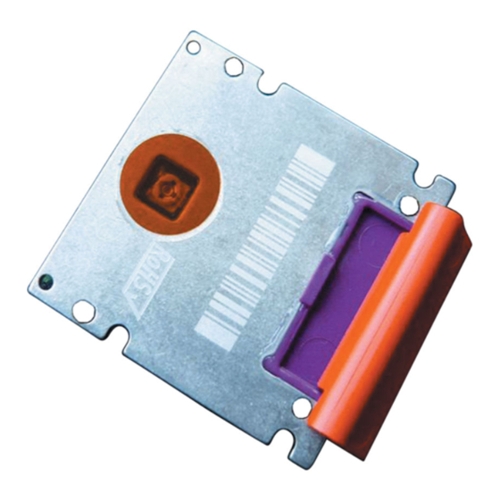
3.1.9 Serial number The printhead serial number is marked on the rear of the printhead as shown in figure 3.1 XJ128 Guide to Operation Xaar Document no: D031010302 Version A Page 12... -
Page 14: Product Specifications
These specifications can vary according to printhead integration and system set-up. The specifications listed in table 3.1 are based upon testing carried out by Xaar under laboratory conditions with approved inks. In a customer application, some specifications such as linear speed, resolution and throughput, together with the final print quality and machine output, will be subject to the design of the machine and the number of passes required to achieve the print quality and coverage desired. -
Page 15: Printhead Life
Although this document does not cover these factors extensively, many of these issues can be discussed with your local sales engineering representative, who can provide further details and guidance to help printhead integration. XJ128 Guide to Operation Xaar Document no: D031010302 Version A Page 14... -
Page 16: Mechanical Guide
XJ128 and XJ128 Plus Printhead Mechanical Guide Before beginning a design phase with Xaar printheads, please ensure that you have obtained the latest printhead drawings from Xaar Sales Engineering. See section 11 of this document for further information. 4.1 Channel numbering and side definition Looking directly at the nozzle plate on the printhead, with the nozzles pointing towards you and the ink inlet pointing away from you, nozzle 1 is on the right side of the printhead. -
Page 17: Printhead Mounting
These should be used as a guide to aid quick and easy mounting and alignment of the printhead into appropriate mounting systems. The mechanical drawing in Appendix D has details of the reference dimensions. The datums are shown in figure 4.3. XJ128 Guide to Operation Xaar Document no: D031010302 Version A Page 16... -
Page 18: Print Distance
The XJ128 printhead is designed to be mounted at an angle, relative to the substrate, to achieve the desired printing resolution. Mounting the printhead at a more acute angle results in a higher vertical printing resolution. XJ128 Guide to Operation Xaar Document no: D031010302 Version A Page 17... -
Page 19: Thermal Management
Please refer to the Ink and Printhead User Guide for the recommended operational temperature or temperature range of the printhead for the specified ink. ‘Single-pass’ printing based upon testing using oil-based inks on porous substrates XJ128 Guide to Operation Xaar Document no: D031010302 Version A Page 18... -
Page 20: Ink Connection
The ink inlet port has an OD of 3.1mm. This is also shown on the mechanical drawing in Appendix D. A 4mm OD/3mm ID tubing is recommended when supplying ink to the XJ128 printhead. XJ128 Guide to Operation Xaar Document no: D031010302 Version A Page 19... - Page 21 5m prior to entering the printhead. This should be done as part of the ink delivery system, please refer to the section 7 for more detail. XJ128 Guide to Operation Xaar Document no: D031010302 Version A Page 20...
-
Page 22: Mechanical System Design
’damping’ in the ink supply, the type of ink and the ambient temperature. The effects of system vibration can also be seen in the final print. Typical effects are light-and-dark banding, caused by pressure fluctuations and stitching errors. XJ128 Guide to Operation Xaar Document no: D031010302 Version A Page 21... -
Page 23: Electrical Functions
Table 5.1 details the pin out of the electrical connector and the functions of each signal. The electrical interface is common for all XJ128 printhead models. Figure 5.1 shows the pin-out convention for the XJ128 printhead. Figure 5.1 – XJ128 printhead pin-out convention XJ128 Guide to Operation Xaar Document no: D031010302 Version A Page 22... -
Page 24: Signal Level Definition
This is achieved holding the signal to logic ground (GND). High Level represents a logic “1” This is achieved holding the signal to logic power supply voltage (VDD). Pull-down resistor inside printheads: 2-30k XJ128 Guide to Operation Xaar Document no: D031010302 Version A Page 23... -
Page 25: Signal Descriptions
Active low, asynchronous reset of the driver chip sequence logic. nReset will not reset the contents of the input data shift registers. MOSI Serial data input (Master Out Slave In). Print data is loaded through this line. XJ128 Guide to Operation Xaar Document no: D031010302 Version A Page 24... -
Page 26: Electrical Connection To The Printhead
The electrical interface connector is a 30-pin connector. The printhead interface makes use of an AMP™ connector type: “AMP™ 30 pin receptacle board-to-board connector”. The AMP™ part number for the printhead connector is: 6-176913-0 (female). XJ128 Guide to Operation Xaar Document no: D031010302 Version A Page 25... -
Page 27: Grounding And Isolation
The low voltage ground (GND), and the high voltage grounds (GNDL and GNDH) must not be joined or grounded at any other point. Refer to section 6.3.1 for detail on grounding schemes. XJ128 Guide to Operation Xaar Document no: D031010302 Version A Page 26... -
Page 28: Electrical Specifications And Data
Allow sufficient time for the decoupling capacitors inside the printhead to become charged or discharged during the power up or power down sequence. Due to the design of the power supply no XJ128 Guide to Operation Xaar Document no: D031010302 Version A Page 27... - Page 29 100 s ACTIVE ACTIVE Table 6.4 - Power down/off sequence Power-down sequence Power-on sequence VPPH/VPPL VPPH/VPPL nRESET nRESET Power on Power down Figure 6.1 – Power on/down sequencing XJ128 Guide to Operation Xaar Document no: D031010302 Version A Page 28...
-
Page 30: Recommended Electrical Operating Conditions
Table 6.7 shows the typical and maximum power consumption expected when operating the XJ128 printhead. Typical Power Consumption Max Power Consumption Unit XJ128/200 Watts XJ128/200 Plus XJ128/360 Watts Table 6.7 – Power consumption of XJ128 printhead XJ128 Guide to Operation Xaar Document no: D031010302 Version A Page 29... -
Page 31: Temperature Compensation
Higher temperatures give lower viscosity and therefore require a lower driver chip voltage. Driver chip voltage 23 Volt Temperature (deg C) 22 C Figure 6.2 - Temperature compensation ‘curve’ example XJ128 Guide to Operation Xaar Document no: D031010302 Version A Page 30... -
Page 32: Data Structure
A-B-C. When the PHO signal is set at a high level (active), the “Reversed cycle order” is used, which means that the used printing order of the groups is C-B-A. XJ128 Guide to Operation Xaar Document no: D031010302 Version A Page 31... -
Page 33: Phase Triggering
ACTIVE Nss2 INACTIVE INACTIVE INACTIVE INACTIVE INACTIVE INACTIVE MOSI CH 64 CH 63 CH 62 CH 3 CH 2 CH 1 Table 6.11 - Print data loading order XJ128 Guide to Operation Xaar Document no: D031010302 Version A Page 32... - Page 34 The timings of these signals shown are tabulated in table 6.12. Figure 6.4 – XJ128 print data loading and control signals Figure 6.5 – Further timings for XJ128 control signals XJ128 Guide to Operation Xaar Document no: D031010302 Version A Page 33...
- Page 35 0.2 * VDD MISO, READY, nFAULT, Iload = max 4mA, VDD = 4.5V MISO, READY, nFAULT, Iload = max 4mA, VDD = 4.5V Table 6.13 – Recommended electrical operating conditions XJ128 Guide to Operation Xaar Document no: D031010302 Version A Page 34...
-
Page 36: Electrical System Design
Electrical inputs into the printhead enclosure from the power source and/or PC are suggested through a bulkhead electrical connector. Voltage supplies VDD, VPPH and VPPL should be isolated. XJ128 Guide to Operation Xaar Document no: D031010302 Version A Page 35... -
Page 37: Cable Lengths And Signals
The printing system should be independently tested for EMC conformity. Any consequences resulting from the use of this equipment in unapproved environments are not the responsibility of Xaar. Xaar recommends that the compatibility of this equipment should be suitably tested in each un-approved environment before use. -
Page 38: Ink Supply System Design
The Ink and Printhead User Guide document details the materials that have been tested and satisfy Xaar’s compatibility requirements. It is recommended that ink supply systems use only these Xaar compatibility approved components. The 'same' material from different manufacturers can yield totally different materials compatibility results. -
Page 39: Providing A Negative Pressure Ink Supply
The ink supply pressure can be easily changed by moving the ink supply reservoir, up or down, relative to the printhead. Open to atmosphere -ve head of ink Figure 7.1 – Gravity fed ink supply system XJ128 Guide to Operation Xaar Document no: D031010302 Version A Page 38... -
Page 40: Vacuum Fed Negative Pressure Ink Supply
Vacuum NOT TO SCALE Figure 7.3 - Ink supply system components (system shown – vacuum fed ink supply) XJ128 Guide to Operation Xaar Document no: D031010302 Version A Page 39... -
Page 41: Small Ink Reservoir
The following process details how to clean ink supply components that use materials that are compatibility approved by Xaar. XJ128 Guide to Operation Xaar Document no: D031010302 Version A Page 40... -
Page 42: Filling The Printhead
Ink supply system should be assembled System should be flushed with the appropriate Xaar flushing solution, please refer to the Ink and Printhead User Guide documentation for the appropriate solution The system should be purged of flushing solution ... - Page 43 The XJ128 printhead should then be correctly primed with ink and ready to start printing. ‘Printhead Maintenance’ Purging, wiping and general maintenance procedures are detailed in section 8, of this document. XJ128 Guide to Operation Xaar Document no: D031010302 Version A Page 42...
-
Page 44: Maintenance, Reliability And Lifetime
Depending upon the system a maintenance carriage may need to move into position to perform the maintenance. XJ128 Guide to Operation Xaar Document no: D031010302 Version A Page 43... -
Page 45: Short-Term Maintenance
If the printhead has an operational temperature different to that of ambient then a pressure purge could introduce a temperature drop and affect performance, therefore a “re-warming” period may be required before operation can resume. Ink and system dependant XJ128 Guide to Operation Xaar Document no: D031010302 Version A Page 44... -
Page 46: Vacuum Purge
To prevent the wiper from scratching the surface of the nozzle plate, wiping must not be carried out on a dry nozzle plate. Normally a purge is performed prior to wiping. XJ128 Guide to Operation Xaar Document no: D031010302 Version A Page 45... -
Page 47: Vacuum Wiping
XJ128 and XJ128 Plus Printhead Excessive wiping can scratch the nozzle-plate. A soft (SH 30) fluoroelastomer wiping blade available from Xaar. Please contact your appointed sales engineer for details. 8.3.4 Vacuum wiping The vacuum-wipe maintenance technique has two main functions: ... -
Page 48: Ink Spitting
Some caps may be filled with solutions to help prevent the drying out of nozzles when using volatile inks. XJ128 Guide to Operation Xaar Document no: D031010302 Version A Page 47... -
Page 49: Image Processing
bitmap (.bmp), jpeg (.jpg), Photoshop (.psd). Bitmap files are required to print with a Xaar evaluation kit. A binary image is saved as a 1-bit bitmap whilst a greyscale bitmap is saved as a 4-bit bitmap. Tiff files are a high quality, high memory image type. Jpeg files can be used to compress image data. -
Page 50: Image Processing Software
The required format for printing with Xaar printheads is CMYK (images made from the primary colours cyan, magenta, yellow and black). This often means the colour space of an original scanned digital image has to be changed from RGB to CMYK although images are also scanned in CMYK and digital cameras can record images directly in to a CMYK format. -
Page 51: Processing An Image
Apply binary printing pattern such as 'diffusion dither' in Photoshop Save in 1-bit bitmap format Is image Print acceptable for application? Process complete XJ128 Guide to Operation Xaar Document no: D031010302 Version A Page 50... -
Page 52: Resolution And Sizing
Enter required pixel or print size Proportions between the horizontal and vertical measurements of the image can be ‘Constrain constrained. Check Proportions’ box Figure 9.3 - Image size box in Photoshop XJ128 Guide to Operation Xaar Document no: D031010302 Version A Page 51... -
Page 53: Changing Colour Space
As a further step the pixel values in a digital image may be suppressed to suit the substrate to be printed on to. This can be performed by a number of pieces of image processing software including Photoshop where a curve can be applied. XJ128 Guide to Operation Xaar Document no: D031010302 Version A Page 52... -
Page 54: Splitting Ink Channels
Select the small triangle from the resulting box to ‘split pull down channel menu. Select channels’ Monochrome images of the 4 colour channels are now produced Figure 9.6 - Channels dialogue box in Photoshop XJ128 Guide to Operation Xaar Document no: D031010302 Version A Page 53... -
Page 55: Binary Patterning Methods
A pattern must be applied to a monochrome image to allow image data to be represented by a single pixel intensity. Some of the different patterns include: Figure 9.7 - Pattern dither Figure 9.8 - Diffusion dither Figure 9.9 - Halftone screen XJ128 Guide to Operation Xaar Document no: D031010302 Version A Page 54... -
Page 56: Saving An Image For Printing
The processed monochrome images need to be saved in the correct format for the printer driver software. If using a Xaar evaluation kit this format will be a 1-bit bitmap (.bmp) This can be performed by a number of pieces of image processing software including Photoshop ... -
Page 57: Xj128 Image Transformation
The nozzle positions are superimposed on the figures to show the relative positions of the printed dot position to the printhead nozzles. Figure 9.12 – XJ128/360 rear view XJ128 Guide to Operation Xaar Document no: D031010302 Version A Page 56... -
Page 58: Extraction Of Image Data
Figures 9.14 and 9.15 show the top 29 nozzles of the printhead positioned over a section of the bitmap to be printed. XJ128 Guide to Operation Xaar Document no: D031010302 Version A Page 57... - Page 59 9.16. This is then the orthogonal image that should be used to load into the printhead driver system. Figure 9.16 - Bitmap adjusted for XJ128/200 printhead XJ128 Guide to Operation Xaar Document no: D031010302 Version A Page 58...
-
Page 60: Trouble Shooting
8.2 of this document. 10.2 Returning printhead(s) to Xaar Should you have any reason to return a printhead to Xaar please contact your local sales engineer and refer to the document XCP001.pdf. Failure to do so could void warranty claims. -
Page 61: Feedback And Support
This manual covers the functionality of the XJ128 printhead. As you use this manual, you may have ideas as how it could be improved or modified such to enhance its usefulness to others. Xaar would welcome your comments and suggestions, as well as reports of any errors, which may have found their way into the manual. -
Page 62: Appendices
The lead oxide content is less than 1% of the entire printhead weight. XJ128 Guide to Operation Xaar Document no: D031010302 Version A Page 61... -
Page 63: Appendix B, Document History And Changes
Minor document changes from the previous edition are given in the revision history chapter. Major revisions are assigned a new suffix. Publications are available from your regional office. XJ128 Guide to Operation Xaar Document no: D031010302 Version A Page 62... -
Page 64: Appendix C, Patents, Trademarks And Product Marking
Xaar printheads are covered by the following US patents and corresponding equivalents in other territories. US Patent Numbers: 4879568,5016028,5003679,4887100,5361084,5512922. Xaar may also have other patents or patent applications pending covering subject matter in this document. The furnishing of this document does not give license to these patents. Trademarks... -
Page 65: Ce Compliance And Working Environment
This product was designed to fulfil the EMC requirements specified for “light industrial environments”. Xaar cannot approve the product to be used in other classifications of environment, e.g. “medical” or “industrial”. Any consequences resulting from the use of this equipment in unapproved environments are not the responsibility of Xaar. -
Page 66: Appendix D, Mechanical Drawing
XJ128 and XJ128 Plus Printhead Appendix D, Mechanical drawing XJ128 Guide to Operation Xaar Document no: D031010302 Version A Page 65... - Page 67 EDGE/CORNER BREAKS INSIDE MAX: --.-- 2000-01-17 OUTSIDE MAX: --.-- APPROVED D-D (10 : 1) TITLE XAAR CONFIDENTIAL&PROPRIETARY TECHNICAL INFORMATION 128 CHANNEL PRINT HEAD, REF DWG XaarJet AB SHEET SIZE SCALE DATE DRAWING NUMBER Elektronikhöjden 10 SHEET SE-175 26 JÄRFÄLLA, SWEDEN 1 ( 1 ) 2.5:1...
-
Page 68: Appendix E, The Xaar Flex-Cable
Figure D1 - Pin connections in the XaarJet cable The flex cable supplied by Xaar reverses the order of pin numbering on the ZIF connector. This means that pin 1 on the ZIF connector goes to pin 30 in the print head. -
Page 69: Glossary
A single bad of print produced by one pass of the printhead. Temperature Compensation Non-wetting coating Waveform The drive signal applied to the PZT wall to produce a pressure wave in the channel. XJ128 Guide to Operation Xaar Document no: D031010302 Version A Page 67... -
Page 70: Index
13, 14, 41, 44 Printhead maintenance 41, 42 protective cap 8, 64 Safety Instructions serial number shared wall 8, 30 shear mode static Temperature compensation vertical resolution 17, 53 XJ128 Guide to Operation Xaar Document no: D031010302 Version A Page 68...
Need help?
Do you have a question about the XJ128 Series and is the answer not in the manual?
Questions and answers