
Summary of Contents for MicroStep-MIS MSB780
- Page 1 MSB780, MSB780X, MSB780X transfer standard Digital Barometers Version 1.25 User’s Guide October 17, 2017...
- Page 2 Editorial team: Adam Krovina, Ján Mikulka, Ján Hudec Firmware version This version of user guide describes functionality of firmware version 097. Hardware version This version of user guide describes functionality of hardware MSB780 V2 and MSB780X V2.0. Address MicroStep-MIS Monitoring and Information Systems, ˇ...
- Page 3 MSB780(X) - User’s Guide Typographical conventions Throughout this guide, several typographical conventions are used to help reader to follow in- structions and identify the important information. The special notes: Note: Air must be used as a pressure medium during calibration.
-
Page 4: Table Of Contents
2.6 Serial interface (RS-232) ....... 2.7 Connecting MSB780 or MSB780X to PC ..... . . - Page 5 MSB780(X) - User’s Guide 4.1 Cleaning .........
- Page 6 MSB780(X) - User’s Guide 6.10 “seri” Set communication settings for user RS-232 ....6.11 “echo1” Enable echo ........
- Page 7 MSB780(X) - User’s Guide 6.35 Adjustment commands ....... . .
- Page 8 8.1 Introduction to SDI-12 ....... . . 8.2 SDI-12 commands supported by MSB780 ..... .
- Page 9 MSB780(X) - User’s Guide 8.15 aXV! Get extended verification ......8.16 Setting parameters via SDI-12 ......
- Page 10 MSB780(X) - User’s Guide 14 History of changes 14.1 V 1.1 ......... . .
- Page 11 MSB780(X) - User’s Guide 14.25 V 1.21 ......... . 102 14.26 V 1.22 .
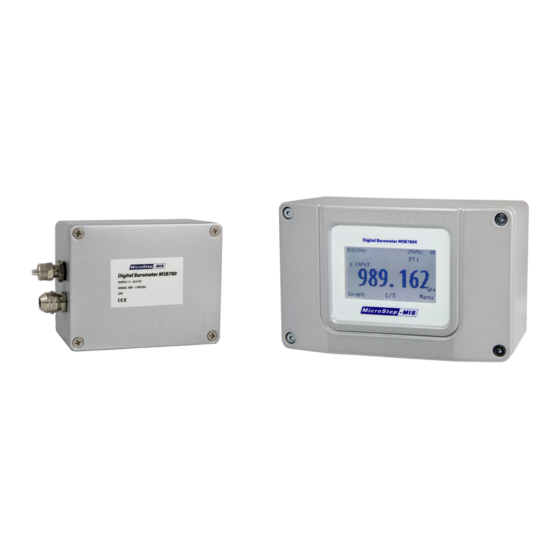
- Page 12 MSB780X is extended version of MSB780. It features pressure transducer of the same pre- mium quality as MSB780, but allows using also two and three pressure transducers in one unit. MSB780X comes also in a brand new design with touchscreen display option.
-
Page 13: Hardware
The terminals for connecting of wires are placed inside the device – unscrew 4 screws and remove the cover to access the terminals. The description of MSB780 terminals is in the figure 1 . Description of MSB780X terminals is in the figure 2... - Page 14 MSB780(X) - User’s Guide Figure 1: MSB780 terminals Figure 2: MSB780X terminals...
-
Page 15: Power Saving Mode
0<cr> 2.6 Serial interface (RS-232) Serial interface can be used to connect MSB780 or MSB780X sensor to a datalogger, or to a PC. To connect to RS232 computer port, a serial cable is needed. Wiring of a RS-232 to PC cable with DB9 connector can be found in table 1 Standard serial interface supports asynchronous communication at speed 9600 bps. -
Page 16: Connecting Msb780 Or Msb780X To Pc
2.7 Connecting MSB780 or MSB780X to PC To connect MSB780 or MSB780X to PC use serial cable (as described above). If the PC does not feature a RS-232 port, a RS-232 to USB convertor may be used. After the sensor is con- nected to PC, use a standard terminal program. -
Page 17: Msb780X Transfer Standard Version
MSB780(X) - User’s Guide Table 4: Service serial port parameters Service serial port Baud Rate 230400 Data Bits Parity None Stop bits In case you have available 3.3 V TTL UART to RS-232 converter available, the service cable may be built-up using schematic in Figure 3... - Page 18 MSB780(X) - User’s Guide Figure 4: MSB780X transfer standard The default accessories within the MSB780X transfer standard are listed in table 5 Table 5: MSB780X transfer standard - list of default accessories Number Accessory Transport case Foam interior MSB780X transfer standard with built-in battery...
-
Page 19: Connecting The External Probe To The Transfer Standard
MSB780(X) - User’s Guide 3.1 Connecting the external probe to the transfer standard When the relative humidity and temperature measurements are to be done, the external RHT175 probe must be connected. Please follow the figure 5 . Use the dedicated cable with connectors. -
Page 20: Turning The Transfer Standard On/Off
MSB780(X) - User’s Guide 3.2 Turning the transfer standard on/off To turn the transfer standard power on/off, use the power button, see the figure 7 . If the transfer standard won’t turn on, please recharge it’s battery (follow section 3.3 3.3). -
Page 21: Using The Transfer Standard With Aa Batteries
MSB780(X) - User’s Guide Figure 9: Connection of a car cigarette lighter plug to the transfer standard 3.4 Using the transfer standard with AA batteries If the battery is empty and there is no way to recharge the battery, it is also possible to use four AA batteries to power the transfer standard. -
Page 22: Transfer Standard Connectors Description
MSB780(X) - User’s Guide Figure 11: Using the transfer standard with an AA battery pack Figure 12: Connecting the transfer standard to RS-232 The battery must be charged enough to power the transfer standard during the computer con- nection, unless you have a special cable, that can provide both power and RS-232 connection at one time (not supplied by default). -
Page 23: Terminals Of The Transfer Standard
MSB780(X) - User’s Guide Figure 13: Description of the transfer standard inputs/outputs Table 6: Description of the transfer standard inputs/outputs Item Description Power button Pressure port External probe connector Power in and communication connector Touch screen display Dust caps To adjust the external probe reading, please refer to the RHT175 User guide, sections RH adjustment, temperature adjustment. -
Page 24: Memory Card
MSB780(X) - User’s Guide Figure 14: Terminals of the MSB780X Transfer Standard 3.9 Memory card Memory card is type micro SDHC and used for saving measurement data. Memory card is inserted with the electrical contacts into inside the MSB780X transfer standard. See figure 15... -
Page 25: Maintenance
MSB780(X) - User’s Guide Figure 15: Inserting memory card into MSB780x transfer standard 4 Maintenance 4.1 Cleaning Clean the barometer enclosure with a soft, lint-free cloth moistened with mild detergent. Check the hoses inside the barometer. If some dirt or insects got inside, it may cause clogging of the hose and incorrect pressure reading. -
Page 26: Compensation Sensor Exchange Procedure
MSB780(X) - User’s Guide 4.4 Compensation sensor exchange procedure 4.4.1 Compensation sensor - maintenance To check the compensation sensor for correct function, follow the procedure below. A relative humidity measuring instrument is required for this procedure. Open the barometer lid. If you have version MSB780X with display, disconnect the display cable from the connector. -
Page 27: Compensation Sensor Faq
MSB780(X) - User’s Guide Table 7: Relative humidity dependence of MSB780 and MSB780X Maximum value of pressure correction according to RH Temperature Relative humidity Correction -50 C to 10 C (0 to 100) [% RH] < 0.1 hPa -50 C to 23 C (0 to 100) [% RH] <... -
Page 28: Calibration And Adjustment
User of MSB780 or MSB780X is responsible for calibration of the barometer in appropriate interval, or when there is a reason to believe, that the MSB780 or the MSB780X is not performing within acceptable limits. If calibration results show impermissible measurement error, the error can be removed using adjustment commands via serial interface. -
Page 29: Adjusting Msb780X With More Than One Transducer
4. Add the computed correction value to the old q coefficient value. In the example 0 + (-0.24) = -0.24. This is the new q value. 5. Write the new k and q values to MSB780 or MSB780X memory using command cset<cr>, as documented in section 6.36 6.36... -
Page 30: More Than 2 Pressure Points Adjustment
7 should be used. Using calculator, computer program or online calculator is advised. After computing the coefficients they need to be stored in MSB780 or MSB780X memory the same way, as in previous section. n¯ x ¯ y n¯ x... -
Page 31: Caset" Adjust The Analog Output
4. Repeat the previous point until you have as many calibration points you want. 5. Compute the coefficients using 6 and 7 6. Write the new k and q values to MSB780 or MSB780X memory using command cset<cr>, as documented in section 6.36 6.36 on page 49 5.7 “caset”... -
Page 32: And Rs-485 Commands
MSB780(X) - User’s Guide Table 8: Range for adjust analog output Parameter Mode / Range 0 .. 5 V 0 .. 10 V 0 .. 20 mA 90% set, insert value you see at output<cr><lf> 18.0058<cr> k=0.999682 q=0.000026<cr><lf> wait.. OK<cr><lf>... - Page 33 MSB780(X) - User’s Guide Table 9 – continued from previous page Command Short description Page addr change the address in POLL mode. addr? get actual address in POLL mode. open access to command mode in POLL mode. close close command mode in POLL mode.
-
Page 34: Basic Commands
MSB780(X) - User’s Guide Table 9 – continued from previous page Command Short description Page caset adjust the analog output Note: Changed settings are immediately stored in FLASH, and will persist after power loss (reset). Storing parameters in FLASH is indicated by printing message: wait..OK<cr><lf>... -
Page 35: Cnf?" Print Configuration
MSB780(X) - User’s Guide RH: 35.201<cr><lf> P result - P: 1003.012, Pqfe: 1003.012, Pqnh: 1003.012<cr><lf> The example shows result of the d<cr> command of a two transducer version MSB780X. Pres- sure measurements for the two transducers follow after P: in hPa unit. The resulting pressure is also outputted. - Page 36 MSB780(X) - User’s Guide cnf?<cr> Conf:<cr><lf> model : MSB780X<cr><lf> display connected, v2<cr><lf> probe : OK, SN: 20B1701NN123<cr><lf> serial : MSB780X-2.0-1709-3DTS-004<cr><lf> fw. ver : 097<cr><lf> Sensor 1 OK<cr><lf> Sensor 2 OK<cr><lf> Sensor 3 OK<cr><lf> Sensor 1 s.n. 00225417<cr><lf> Sensor 2 s.n.
- Page 37 MSB780(X) - User’s Guide model - model identification. display - idicates the state of the display and its version. probe - idicates the state of the external probe and its serial number. serial - device serial number. fw. ver - version of the firmware.
-
Page 38: Errors" Print Error Message
MSB780(X) - User’s Guide Table 10: Error state iterpretation Reply acronym Error interpretation 1000000 Precise clock of RTC failure 0100000 Precise clock of CPU failure 0010000 bsen Error of some of the three transducers 0001000 Error of pressure weighted average value or difference limit 0000100 flash... -
Page 39: Help" Display Help
MSB780(X) - User’s Guide 6.8 “help” Display help The help<cr> command displays list of available serial interface commands with a short de- scription. 6.9 “boot” Restart device This command can be used to restart the device. Example: boot<cr> 6.10 “seri” Set communication settings for user RS-232 Possible baud rates are the following: 600, 1200, 2400, 4800, 9600, 19200, 38400, 57600, 115200, 230400. -
Page 40: Echo0" Disable Echo
6.13 "form" Change output message format This command is used to set a format of the message being output by MSB780 or MSB780X after SEND<cr> command, or automatically if run mode is on. The format string can be up to 126 characters long. - Page 41 MSB780(X) - User’s Guide Table 11 – continued from previous page Field Description Temperature of pressure transducer 2 Temperature of pressure transducer 3 DP12 Pressure diference (P1 - P2) DP13 Pressure diference (P1 - P3) DP23 Pressure diference (P2 - P3) Line feed character.
-
Page 42: Form?" Get Actual Output Message Format
MSB780(X) - User’s Guide ple: form<cr> Write formatted string for FORM: /<cr> FORM format is OK<cr><lf> |! 997.34<cr><lf> |<cr><lf> wait..OK<cr><lf> 6.14 "form?" Get actual output message format To get actual output message format, use the form?<cr> command. Example: form?<cr> start>P RN <end<cr><lf>... -
Page 43: Smode?" Get Actual User Port Start-Up Operating Mode
MSB780(X) - User’s Guide Table 12: smode command options Field Description The barometer will not send message automatically. The barometer will not STOP react to SEND<cr> command in this mode. Command mode is open all the time. The barometer will send message automatically with period set by intv<cr>. -
Page 44: Intv?" Get Actual The Outputting Interval For Run Mode
MSB780(X) - User’s Guide 6.18 "intv?" Get actual the outputting interval for RUN mode To Get actual the outputting interval for RUN mode, use the intv?<cr> command. Example: intv?<cr> INTV: 1 s<cr><lf> 6.19 "avrg" Averaging time The avrg<cr> is used to set and inspect the averaging time during which the individual mea- surement samples are integrated to get an averaged pressure reading. -
Page 45: Addr" Change The Address In Poll Mode
MSB780(X) - User’s Guide avrg?<cr> Averaging time = 100 s<cr><lf> 6.21 “addr” Change the address in POLL mode Addresses are required only for POLL mode. It is not supported on service port. Use the addr a<cr> command to set barometer address, where a is address (0 . . . 255)(default = 0). -
Page 46: Send" Read The Output Message In Poll Mode
! 995.17<cr><lf> 6.26 “unit” Change the measurement unit MSB780 and MSB780X internally work with hPa unit. Using this command, it is possible to change output data unit for each pressure quantity separately. The change applies immediately for all outputs (p, d, send commands, LCD screen, etc.), apart from SDI command R0 which always returns result in basic units (hPa). -
Page 47: Unit?" Get Actual Measurement Unit
MSB780(X) - User’s Guide 6.27 “unit?” Get actual measurement unit This command lists all quantities and actual unit of each. 6.28 “cnfdef” Set default configuration This command reverts configuration to factory defaults, i.e.: - default units (hPa) for all pressure quantities, - zero values for hqnh, hqfe, hhcp, - tqfe and tqfea temperature for QFE calculation to 20 C, - maximum permissible pressure difference between transducers (DPMAX) to 1.0... -
Page 48: Terminal Rs485" Temporarily Redirect The Service Port To
MSB780(X) - User’s Guide For example, the user would like to set the RS-232 baud rate via service port. First the user redirects to the RS232 port: terminal rs232<cr> Terminal mode is active. Close it with command "tclose" !<cr><lf> RS232 >... -
Page 49: Type
MSB780(X) - User’s Guide Example: dir e:<cr> DIR e:<cr><lf> Disk E DIR:<cr><lf> File name Size [B] Date dmy Time hms<cr><lf> 16030102.CSV 952 28.03.2016 10:32:22<cr><lf> 17030101.CSV 2954 15.03.2017 14:58:04<cr><lf> 17042505.CSV 1826844 25.04.2017 21:23:02<cr><lf> 17042601.CSV 1327 26.04.2017 03:02:02<cr><lf> 17050801.CSV 10772600 09.05.2017 00:13:10<cr><lf>..." Print File -
Page 50: Adjustment Commands
In the following chapters commands for adjusting the barometer are described. 6.36 “cset” Set adjust coefficients This command enables to adjust the MSB780 barometer by entering two linear coefficients - offset and gain. If the barometer contains more transducers, two coefficients for each transducer can be set. -
Page 51: Cnf?" Get Actual Adjust Coefficients
MSB780(X) - User’s Guide cset<cr> Select sensor [ 1 2 ] : 1<cr> CSET for sensor 1 : [ k q ] "0.1234"<cr><lf> Set new ’k’ coefficient:1.00034<cr> k = 1.000340<cr><lf> Set new ’q’ coefficient:0.03<cr> q = 0.030000<cr><lf> wait..OK<cr><lf> In this example, coefficients for transducer 1 were updated. -
Page 52: Adjdef" Set Default Adjustment
MSB780(X) - User’s Guide 6.40 “adjdef” Set default adjustment This command resets all adjustment coefficients k, q to their default values. For model MSB780X with more pressure transducers, this command resets coefficients for all of them. This command also resets adjustment coefficients of analog output. -
Page 53: Hqfe" Set Altitude For Qfe Corrected Pressure
MSB780(X) - User’s Guide Table 14: Valid ranges for HQFE parameter Valid ranges for HQFE parameter Unit Minimum Maximum Example: icaodigits<cr> Actual setting: no truncate<cr><lf> Insert max nr. of decimal digits [0..6 or off(means no truncate)]: 1<cr> wait..OK<cr><lf> 6.44 “hqfe” Set altitude for QFE corrected pressure Using this command you can set hqfe, which is height difference between the barometer eleva- tion and official aerodrome elevation. -
Page 54: Hqnh" Set Altitude For Qnh Corrected Pressure
MSB780(X) - User’s Guide g is gravitational acceleration 9.81 m.s R is gas constant 287 J.kg is temperature in K (see tqfe and tqfea commands) QF E or (if ICAO mode turned on) β ( h QF E QF E = p... - Page 55 MSB780(X) - User’s Guide Table 15: Valid ranges for HQNH parameter Valid ranges for HQNH parameter Unit Minimum Maximum 5000 16000 where is station elevation in m QN H g is gravitational acceleration 9.81 m.s R is gas constant 287 J.kg T is standard temperature 288.15 K...
-
Page 56: Tqfe" Set Temperature For Qfe Corrected Pressure
MSB780(X) - User’s Guide Table 16: Valid ranges for HHCP parameter Valid ranges for HHCP parameter Unit Minimum Maximum 6.46 “tqfe” Set temperature for QFE corrected pressure This command sets default temperature for calculation of the QFE corrected pressure and saves it to FLSAH memory. -
Page 57: Hqfe?" Get Altitude For Qfe Corrected Pressure
MSB780(X) - User’s Guide Set height difference in m, ranges -30.00 .. 30.00 : 0.1<cr> wait..OK<cr><lf> In the example the new HHCP parameter was set to 0.1 m. 6.49 “hqfe?” Get altitude for QFE corrected pressure hqfe?<cr> HQFE: 0.00 m<cr><lf>... -
Page 58: Dt" Get Date And Time
MSB780(X) - User’s Guide Example: hhcp?<cr> HHCP: 0.10 m<cr><lf> 6.54 "dt" Get date and time Use this command to print the current date and time. Example: dt<cr> Actual date and time: 10:49:07 28.03.2016 Monday<cr><lf> Date and time format: HH:MM:SS DD.MM.YYYY <cr><lf>... -
Page 59: Display Access
MSB780(X) - User’s Guide wait..OK If you enter empty string (<cr> only) the PIN will not be asked and the access via LCD is free, unprotected. Factory default PIN is "1234". 7 Display access This section refers only to MSB780X versions with touchscreen display option. - Page 60 MSB780(X) - User’s Guide Battery/charging state (battery version only) Barometer state (State: OK or ER with error number) Quantity and unit which is displayed Pressure trend (PT: icon is displayed 30 minutes after reset) T: temperature from external probe (when connected)
-
Page 61: Graph Screen
MSB780(X) - User’s Guide 7.2 Graph screen Graph view is activated by tapping the Graph button on the main screen. Example of the Graph screen is in the following picture: The graph always shows time on horizontal axis and measured pressure on the vertical axis (with no regard on what is shown on basic screens). -
Page 62: Recording Menu (Logging Data To Sd Card, View In Graph)
MSB780(X) - User’s Guide Periode Quantities Memory – Measuring HQFE HQNH TQFE HHCP DPMAX ICAO settings Edit from LCD – Interfaces SDI12 RS232 RS485 Analog output Ext. probe – System Set Date/Time Diagnostic (allQ) Diagnostic (devs) Baro sensors Serial number Version –... - Page 63 MSB780(X) - User’s Guide Note: You can start recording only if date and time are correctly set. If it is not, you will be automatically redirected to "Set Date/Time" screen Recording screen This screen is used to start and stop recording.
- Page 64 MSB780(X) - User’s Guide Here you can see file name and time/date of storing file (not begin of recording). You can tap "DELETE FILE" which deletes the file after approving with YES button or tap "SHOW GRAPH" which leads to this screen: Select the quantity to plot.
-
Page 65: Measuring Menu (Measurement Settings)
MSB780(X) - User’s Guide Note: Lower periode leads to larger record files and longer time needed for file transfer to PC. Quantity screen (selecting quantities to be recorded) This screen is used for selecting quantities which will be recorded: Use arrows to browse the list of available quantities and MARK/UNMARK button to select/deselect them. - Page 66 MSB780(X) - User’s Guide HQNH - Altitude for QNH corrected pressure TQFE - Temperature for QFE corrected pressure HHCP - Altitude for HCP height corrected pressure DPMAX - Maximum permissible difference between pressure transducers ICAO settings - Mode of QFE and QNH calculation, truncating of QFE and QNH reading Note: These settings can be altered only after allowing it by entering correct PIN code in "Edit...
- Page 67 MSB780(X) - User’s Guide Entered value is accepted only if it is in allowed ragne of the parameter: Range for HQFE: see Table 14 on page 52 Range for HQNH: see Table 15 on page 54 Range for HHCP: see Table 16...
-
Page 68: Interfaces Menu (Settings Of Interfaces)
Screen of Interfaces menu is in the following picture: Screen of SDI12 menu is in the following picture: In this screen you can see the actual SDI-12 address of MSB780 or MSB780X. The SDI-12 address in the example is 6. - Page 69 MSB780(X) - User’s Guide Please use serial commands to change the parameters of interfaces. Screen of Analog output menu is in the following picture: "Range" shows actual range of analog output and its unit, i.e. current/voltage mode. Lower number regards to Q.min value, higher number regards to Q.max value. "V" means that analog output works as voltage source, "mA"...
-
Page 70: System Menu (Date/Time, Diagnostics, Serial/Version Numbers)
MSB780(X) - User’s Guide State - connected or not connected SN - serial number of connected external probe RH - measured value of relative humidity T - measured value of temperature DP - calculated value of dew point 7.8 System menu (Date/Time, diagnostics, serial/version numbers) In system menu you can set date/time and browse diagnostic information, firmware version and... -
Page 71: Display Menu (Shown Quantities, Graph Time-Scale, Backlight Settings)
MSB780(X) - User’s Guide This advanced diagnostic information is mainly for professionals to find a potential problem, if something is wrong with the barometer. Baro sensors: This screen shows serial numbers and calibration numbers of all installed trans- ducers. Serial number: This screen shows serial number of the barometer. -
Page 72: Alarm
MSB780(X) - User’s Guide In "Home screen" submenus you can set which quantities are shown on "basic screens" after starting the MSB780X. Example of Home screen (2/3) is in the following picture: Use arrows to select quantity on the first basic screen or buttons "SET1", "SET2" and "SET3" to adjust quantity in line 1, 2 and 3 of the second and third basic screen. -
Page 73: Reference
Follow the instructions given by the data recorder manufacturer to set up the SDI-12 communication. 8.2 SDI-12 commands supported by MSB780 All SDI-12 commands start with address (a stands for address), and are terminated by !. All SDI- 12 sensor responses start with address (a stands for address), and are terminated by <cr><lf>... -
Page 74: Commands Set
MSB780(X) - User’s Guide 8.3 SDI-12 commands set Table 17: MSB780 SDI-12 commands MSB780 SDI-12 Commands Command Short description Page Address query command. Acknowledge active command. aAb! Address change command. Start concurrent measurement command. aD0! Send data command. Send identification command. -
Page 75: Ai! Send Identification Command
MSB780(X) - User’s Guide 8.5 aI! Send Identification Command This command is used to query sensors for their SDI-12 compatibility level, model number, and serial number. 0I!<cr>013MS-MIS MSB7801.11.2.11505-183 <cr><lf> 8.6 ?! Address Query Command When a question mark (?) is used as the address character with the acknowledge active com- mand (a!), the sensor will respond as if it is being addressed on the SDI-12 bus. -
Page 76: Am1! Start Measurement Command, Return Also Hqfe, Hqnh
0+985.937+986.281+992.741+3.00+55.00<cr><lf> The last two parameters are HQFE [m] and HQNH [m]. 8.10 aD0! Send Data Command This command is used to get data from the sensor. MSB780 does not distinguish between D0, D1 etc. 8.11 aR0! Continuous Measurement (basic units) This command returns last measured value of pressure. -
Page 77: Ar1! Continuous Measurement (User Units)
0D0!<cr>0+0+0+0+0+0<cr><lf> 8.14 aXD1! Send data command from transducer 1 This command is used to get data from the sensor, specifically from transducer 1. If MSB780 has more then one transducer, it can be use commands aXD2!<cr> from transducer 2 and... -
Page 78: Axv! Get Extended Verification
MSB780(X) - User’s Guide aXD3!<cr> from transducer 3. Example: 0XD1!<cr> 0+999.620+10367.5377+0.600085+50.00+0.103364<cr><lf> Where 0 sdi-12 barometer address +999.620 pressure in hPa from transducer 1 +10367.5377 frequency in Hz from transducer 1 +0.600085 voltage in V from transducer 1 +50.00 relative humidity +0.103364 pressure correction from compensation sensor... -
Page 79: Setting Parameters Via Sdi-12
0+2.300000m<cr><lf> The new value of parameter HQFE has been set to 2.3 m and stored to non-volatile memory. List of parameters which can be set is in table 19 Table 19: MSB780 SDI-12 commands Parameters accessible via SDI-12 Parameter Short description... -
Page 80: Amode" Set Analog Output Range
MSB780(X) - User’s Guide Table 20: Analog output ranges Parameter Range 0 .. 1 V 0 .. 5 V 0 .. 10 V 0 .. 20 mA 4 .. 20 mA from 0 V to 1 V from 0 V to 5 V... -
Page 81: Asel" Analog Output Quantity And Scale
MSB780(X) - User’s Guide amode x<cr> wait.. OK<cr><lf> The analog output is now turned off. Important: After setting range, remember to set also the AERR value. 9.2 “asel” Analog output quantity and scale This command is used to select a quantity and range to be displayed on the analog output. -
Page 82: Atest" Analog Output Test
MSB780(X) - User’s Guide 9.3 “atest” Analog output test To test the analog output, use atest command to force a value. The value will be forced until the same command is fed without parameters. The valid range of test voltage / current is the same as current analog output range. -
Page 83: Technical Data
MSB780(X) - User’s Guide 2. one parameter: set new value. Example: aerr 10<cr> Actual error value: 0.000 V<cr><lf> New error value: 10.000 V<cr><lf> wait.. OK<cr><lf> 10 Technical Data 10.1 Quantities Besides pressure, the barometer enables to measure, display, output and watch by alarm sev- eral quantities. -
Page 84: Performance
MSB780(X) - User’s Guide Table 21 – continued from previous page Acronym Meaning Available units hPa, inHg, psi, torr, bar, DP12 pressure difference between transducer 1 and 2 mbar, mmHg, kPa, mmH2O, inH2O hPa, inHg, psi, torr, bar, DP13 pressure difference between transducer 1 and 2... -
Page 85: Analog Output Accuracy
MSB780(X) - User’s Guide 10.3 Analog output accuracy The accuracy of the analog output is calculated with extension factor k = 2 over the temperature range. Range Accuracy Value Range 0 ... 1 V < 0.13 mV 0.0080 % 0.0044 % 0 ... -
Page 86: Drawings
MSB780(X) - User’s Guide * Depends on range setting and load. 10.7 Drawings On the following pages are shown the drawings of barometers MSB780, MSB780X. The dimen- sions are in millimeters. - Page 87 MSB780(X) - User’s Guide Figure 18: Drawing of MSB780...
- Page 88 MSB780(X) - User’s Guide Figure 19: Drawing of MSB780X...
- Page 89 MSB780(X) - User’s Guide Figure 20: Drawing of mounting bracket with PTB330 compatible montage holes...
-
Page 90: Troubleshooting
MSB780(X) - User’s Guide 11 Troubleshooting This section lists several most common symptoms of problems and actions that should be taken in order to solve them. Table 22: Troubleshooting Troubleshooting Problem Possible cause Solution Measure power supply voltage on termi- nals PWR+, GND. -
Page 91: In Case Of Problems
When sending the product back to MicroStep-MIS please try to send a description of problems along with the product. Pack the barometer properly, stuff the package with enough shock- absorbing material in order to prevent it from damage during transport. -
Page 92: Ordering Information
MSB780(X) - User’s Guide 12 Ordering Information In table 23 you can find order codes for different configuration of MSB780 or MSB780X barom- eters. Table 23: MSB780 and MSB780X ordering information Order Code Box type Number of transducers LCD Display... -
Page 93: Firmware Update
13 Firmware update 13.1 Hardware required for firmware update To perform a firmware update of MSB780 or MSB780X a service cable is required. This acces- sory can be ordered from MicroStep-MIS. If your PC/notebook features a RS-232 port, you do not need the USB to RS-232 convertor. -
Page 94: Firmware Loader Software
13.2 Firmware Loader software After the service cable has been properly connected, MicroStep-MIS Firmware Loader software can be used to upload a new firmware. You can obtain this software from MicroStep-MIS. Follow these steps to upload a new firmware to the barometer: 1. - Page 95 MSB780(X) - User’s Guide 2. Choose the firmware file with .mstepfw suffix. Figure 25 3. After selecting the firmware file, you can see the information about the firmware, as seen in Figure 26 4. Select a serial port the barometer is connected to. If there is only one choice, it will be selected automatically.
- Page 96 MSB780(X) - User’s Guide Figure 25: Selecting the firmware file Figure 26: Information about selected firmware...
- Page 97 MSB780(X) - User’s Guide Figure 27: The transferring process...
- Page 98 MSB780(X) - User’s Guide Figure 28: Listing information after successful transfer of firmware...
-
Page 99: History Of Changes
MSB780(X) - User’s Guide 14 History of changes 14.1 V 1.1 Fixed resolution to three decimal places in [hPa] units. Corrected string “0000” to “000” in chapter “Start Measurement Command (aM!). Updated “Principle of operation” chapter, added NOTE on calibration. -
Page 100: 1.3
1.2.1. Changed terminal markings TX, RX to TXD, RXD. Changed line termination from <cr><lf> to <cr>, or <cr><lf>. MSB780 accepts <cr> as an alternative line ending since fw version 12. Changed default echo on to default echo off, with an option to turned echo on using a command. -
Page 101: 1.5
MSB780(X) - User’s Guide 14.9 V 1.5 Updated section 4.4 4.4. 14.10 V 1.6 Updated title photo; MSB780 case changed color from black to silver. Updated section 4.4 4.4. 14.11 V 1.7 Updated values in table 7 on page 26 14.12 V 1.8... -
Page 102: 1.11
Added options P, P1, P2, P3 for FORM command. 14.17 V 1.13 Added commands terminal rs232 and terminal rs485. 14.18 V 1.14 Added page reference to table MSB780 commands and MSB780 SDI-12 commands. Added commands aXD1!, axD2!, aXD3!, aXV! for SDI-12. 14.19 V 1.15 Changed structure of document Added section Power saving mode Changed time in SDI-12 reply of M command: max. -
Page 103: 1.17
MSB780(X) - User’s Guide 14.21 V 1.17 Added specifiers QNH, QFE, HCP, P3H, A3H, TP1, TP2, TP3, DP12, DP13, DP23 for the form command. 14.22 V 1.18 Added SDI-12 commands for setting HQFE, HQNH, TQFE, HHCP, DPMAX, K1, Q1, K2, Q2, K3, Q3 parameters. - Page 104 MSB780(X) - User’s Guide 14.27 V 1.23 Actualized "cnf?" listing Actualized basic screens subsection Added commands avrg, avrg? 14.28 V 1.24 Added: Analog output commands amode, asel, atest, aerr, caset Actualized "cnf?" listing Small corrections in text. 14.29 V 1.25...
Need help?
Do you have a question about the MSB780 and is the answer not in the manual?
Questions and answers