Advertisement
Quick Links
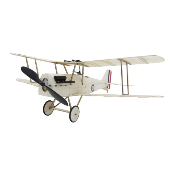
S.E.5a
(Build Instructions)
Specifications
Wingspan: 38 cm
Length: 31cm
Flying Weight: 41
Channels: 3 (Rudder Elevator Throttle)
Suggested Receiver: 3Ch Brick
Motor: 7mm Geared Motor
Airframe Only Kit
(Included Contents)
* Airframe Covering Parts (balsa)
* Airframe Skeleton (hardwood)
* Carbon pushrods
* Wheels and rubber tyre rings
* Fine sand paper
* Control linkages
Complete Kit
(Also contains these items)
* Receiver (brick style 3ch)
* Motor – 7mm Dual Geared
* 140mm Propeller
* Motor and receiver pre-wired (no soldering)
Needed to Complete
* Thick CA Glue
* Micro Phillips Head Screwdriver
* Hobby Knife
* Ruler
* Household Pins
* Hobby Masking or Other Tape
* Receiver Transmitter Charger Battery
* Tweezers
* Patience
* Keen Eyesight
* Steady Hands
Battery Options
The Nanotech 300mah 1S battery is
recommended for best balance.
If using the Nanotech 130mah or similar
battery, you will also need to add some
ballast to the nose.
Advertisement

Summary of Contents for Micron Wings Balsa Craft S.E.5a
- Page 1 S.E.5a (Build Instructions) Specifications Wingspan: 38 cm Length: 31cm Flying Weight: 41 Channels: 3 (Rudder Elevator Throttle) Suggested Receiver: 3Ch Brick Motor: 7mm Geared Motor Airframe Only Kit (Included Contents) * Airframe Covering Parts (balsa) * Airframe Skeleton (hardwood) * Carbon pushrods * Wheels and rubber tyre rings * Fine sand paper * Control linkages...
- Page 2 Before You Start This airframe has been designed to fit together easily with all components precision drilled and CNC cut from high quality balsa and paulownia wood. However, you will be working with very small components, so you will need patience and keen eyesight. We recommend working in a very well lit area and taking a break between stages to rest the eyes and hands.
- Page 4 Step 01 – Removing the Parts Assemble these parts for the first stage of the fuselage. When removing the parts from the sheets take your time and use a hobby knife instead of pressing them out with your fingers. Refer to the images below and glue the various parts in place. Make sure that after gluing the parts on top, you turn it over and clear out the glue from any slots which the bottom parts fit into.
- Page 5 The completed top section Pointing slightly to right Part r is the door hatch. Glue the magnet in place. Step 02 – The Fuselage Frame...
- Page 6 Use a ruler to press down on the body and bend each side piece at this point slightly Glue both sides in place but don’t continue over the top yet. Glue in place the bottom surface and the two side pieces (part H) which go either side of the bottom hatch.
- Page 7 Step 03 – Fuselage Covering Glue the parts below in place starting with part N – the thinner one. Then glue part M in place. Finally glue part 5 in place. Be careful that the glue on the rear of part M doesn’t block the two rectangular holes in the body former where the bottom hatch cover needs to fit.
- Page 8 Step 04 – Base Plate and Engine Cowl With your finger, dab some water on both sides of the fuselage frame and also on the top cover sheet (part 1). Allow the water to soak in and the balsa will be come easily bendable, The top edges of the fuselage sides will need to be trimmed until the meet flush and sit down on the fuselage formers.
- Page 9 Step 07 – Stabilizer Brace Glue part 3 in place but when you do, only glue it at the front. Do not glue it on the bottom to the fuselage sides. Later, the fuselage sides will be cut where the dotted line is and the slice removed to make way for the tailplane to slide in.
- Page 10 Wet the piece of balsa to be bent around the frame on both sides and slowly work it into a curved shape. Then without gluing, tape it to the frame and let it dry to this shape. After the piece is fully dry it can be glued in place.
- Page 11 Apply the waterslide transfers as shown in the image on the left. Lay out your parts the same as in the picture (look at the wing tips and match the longer edge and shorter edge). Note that the shorter wings on the top of the image near the fuselage are actually the top wings (there is a middle section missing which actually makes them longer than the bottom ones once fitted to the plane).
- Page 12 Glue in place the cross brace and the middle section (Part G) Step 09 – Attaching The Wings The next task is to glue on the wings and wing struts. Follow the images below to attach the top and bottom wings. When gluing the wings in place, tape them with modeling masking tape as shown in the above video to align the two surfaces.
- Page 13 Step 10 – Hinging The Control Surfaces Glue in place part ”i” into the tail plane. As this part is important for the strength of the elevators, it’s a good idea to smear a thin layer of glue on both sides where it joins to the balsa. Glue on the hinge strips as shown here keeping them clear of the balsa tabs which join the moving surfaces to the tailplane surfaces.
- Page 14 If you have purchased the complete kit version of this plane, the “ Receiver 24R6CLV11 DSM2 Compatible Linear 5Ch Brick” receiver board will be included. To use this receiver you will need to reverse the direction of the rudder and elevator servos by adjusting settings on your transmitter.
- Page 15 spacers. The outer one can have some glue added to keep it in place. Also glue the carbon axel to the balsa strip. Construct the gun and wind shield as shown here. It is better to glue the gun to the top wing and then glue the gun base to the fuselage so they are touching.
- Page 16 Colour them black with a felt pen and glue them on to the engine cowl in the position marked. Mount the motor as shown here. You will need to add some down thrust by placing 2 pieces of wood under the rear edge of the motor mount. Use a 1mm thick pieces of hardwood offcut from the parts template sheets.
- Page 17 In the next section we will be mounting the receiver. First, refer to the COG (balance point) diagram at the bottom of this document and test the position of your gear to make sure it will balance at the correct point. Mount ther receiver as far forward as possible using the strip of velcro or even better by gluing it in place.
- Page 18 Most importantly, before you attach the control surfaces check that you have the settings such as trims set to zero on the trasnsmitter. Finally use some heat source such as a soldering iron to shrink the heat shrink on the control surface linkages..
- Page 19 The correct point for the centre of balance is shown below. Ensure your plane is balanced at this point. This is a scale aircraft and as in the design of the actual aircraft, the nose is very short. In the actual aircraft, a very heavy motor sat up the front. However, in a model, the motor tends to be much lighter comparatively.
- Page 20 Note: Alternate setup. Instead of a receiver brick, you may choose to use a micro receiver with a brushed speed controller and servos. The dotted square in the receiver mounting board can be cut out and servos mounted instead. The recommended parts for this type of setup are shown below. Alternate Setup Parts List.
- Page 21 A sample flight video – A little windy for this bird, but still able to be flown outside. Further Optional Modifications This model can also be converted to use a conventional receiver with micro servos instead of the standard brick type receiver with linear servos. It can also be modified to have ailerons on the lower wing.
Need help?
Do you have a question about the Balsa Craft S.E.5a and is the answer not in the manual?
Questions and answers