
Summary of Contents for SCHABMULLER TSA Series
- Page 1 Operating and maintenance instructions (translation of original instructions) Motor, pump unit, motor unit, servo unit Version 1.0...
- Page 2 Operating and maintenance instructions Imprint Imprint Schabmüller GmbH Industriestraße 8 92334 Berching Germany Tel.: +49 8462 204-0 Fax: +49 8462 1841 E-mail: info@schabmueller.de Homepage: www.schabmueller.de © Schabmüller GmbH 2019 Distribution as well as duplication of the instructions, use and communication of the contents are forbidden.
-
Page 3: Table Of Contents
Operating and maintenance instructions Table of contents Table of contents 1 General information ..........................5 About these operating instructions ..................5 Further product documentation ................... 5 Motor type-dependent descriptions ..................6 Rating plates ........................7 Options and attachments ..................... 9 Variant examples ....................... - Page 4 Operating and maintenance instructions Table of contents 9 Troubleshooting ..........................50 10 Customer Service and Support ......................52 11 Disposal ............................53 11.1 Cleaning agents, auxiliary materials and operating materials ........... 53 11.2 Scrapping ........................... 53 11.3 Electrical and electronic components ................53 12 Standards ............................
-
Page 5: General Information
Operating and maintenance instructions General information 1 General information 1.1 About these operating instructions The information in these operating and maintenance instructions (hereinafter: operating instructions) has been compiled with great care to ensure that it corresponds to the specifications and use of the motor. These operating instructions for Schabmüller GmbH motors are intended to assist persons entrusted with the corresponding tasks in correctly installing, operating and maintaining this electrical machine. -
Page 6: Motor Type-Dependent Descriptions
Operating and maintenance instructions General information 1.3 Motor type-dependent descriptions These operating instructions apply to all Schabmüller GmbH standard motors. Note: Electrical connections, attachments, maintenance measures, etc. may differ depending on the type of drive or motor. An overview can be found on page 9. To better understand these operating instructions, please first identify your motor type using the information on the rating plate (see page 7and page 8). -
Page 7: Rating Plates
Operating and maintenance instructions General information 1.4 Rating plates 1.4.1 Asynchronous motor Permanent magnet motor / Synchronous reluctance motor The standard rating plates for asynchronous motors, permanent magnet motors and synchronous reluctance motors contain the following information (customer-specific rating plates may differ): Item Designation Serial number... - Page 8 Operating and maintenance instructions General information 1.4.2 DC motor The standard rating plate for DC motors contains the following information (customer- specific rating plates may differ): Item Designation Serial number Material number Type designation Voltage Output Production week Duty cycle Direction of rotation Quality sticker with the number of the final inspector Version 1.0...
-
Page 9: Options And Attachments
Operating and maintenance instructions General information 1.5 Options and attachments Depending on the drive type or motor type (see page 6), the following combinations are possible: Drive motor Pump unit Motor unit Servo unit TSA = asynchronous motor TSL = DC motor TSS = synchronous motor TSR = synchronous reluctance motor = combination possible... -
Page 10: Variant Examples
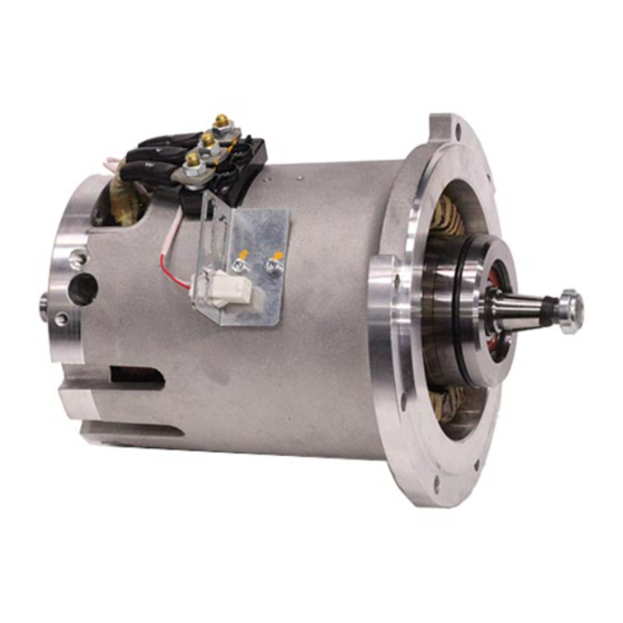
Operating and maintenance instructions General information 1.6 Variant examples Schabmüller GmbH produces hundreds of motor variants for a wide variety of applications. Here you will find examples and excerpts of various applications and motor variants: Application Figure showing motor Characteristics ... - Page 11 Operating and maintenance instructions General information Application Figure showing motor Characteristics DC motor Battery voltage: 24 V…80 V Housing diameter: 100, 102, 112, 125, 150, 178, mm Output: 0.5…10 kW Pump mounting, mounting and shaft ends according to customer specification ...
-
Page 12: Safety
Operating and maintenance instructions Safety 2 Safety 2.1 General safety instructions 2.1.1 Obligations of the operating company Only qualified persons who carry out work on the motors and consistently observe and implement the supplied operating and maintenance instructions as well as the standards and safety instructions mentioned may install, commission and service the motors. - Page 13 Operating and maintenance instructions Safety 2.2.2 Danger signs Danger symbols are used to draw attention to the danger of personal injury. Danger signs Meaning General danger sign Failure to observe the warnings may result in death, serious injury or serious damage. Suspended loads Failure to observe the warnings may result in death, serious injury or property damage due to falling loads.
-
Page 14: Transport And Storage
Operating and maintenance instructions Transport and storage 3 Transport and storage Warranty NOTICE If any damage is discovered after delivery, report it immediately to the transport company, the insurance company and Schabmüller GmbH. Failure to report the discovered damage will void the warranty. The motors are tested and delivered ready for installation. -
Page 15: Storage
Operating and maintenance instructions Transport and storage 3.3 Storage Danger of property damage NOTICE Improper handling during transport and storage can cause damage. Avoid vibrations, falls and humidity during transport Strictly follow all instructions in these operating and maintenance instructions and document this to maintain the manufacturer's warranty ... - Page 16 Operating and maintenance instructions Transport and storage Condition of the protective coating Condition of the paintwork Signs of larvae and insects Ambient temperature Humidity Conditions at the storage location (see page 15) Instructions in the maintenance schedule (see page 46) 3.3.4 Other motor-dependent storage measures Motor characteristic Storage measures...
-
Page 17: Installing The Motor
Operating and maintenance instructions Installing the motor 4 Installing the motor 4.1 Tightening torques for fastening elements Danger of property damage NOTICE For attachments, use the tightening torques specified by the manufacturer If no tightening torques are specified by the manufacturer, refer to the drawing or the table below for tightening torques ... -
Page 18: Mounting The Shaft Sealing Rings
Operating and maintenance instructions Installing the motor 4.2 Mounting the shaft sealing rings Danger of property damage NOTICE Do not scratch or damage the sealing surfaces during disassembly Do not tilt the sealing ring when pressing it in 4.2.1 Removal and replacement The removal of sealing rings is generally not difficult. - Page 19 Operating and maintenance instructions Installing the motor 4.2.2 Installation The sealing edge of the new shaft seal should not come into contact with the old raceway. This can be achieved by: Pressing into the locating bore at different depths ...
- Page 20 Operating and maintenance instructions Installing the motor Examples of the assembly of shaft seals Item Designation Press-in tool Shaft seal Version 1.0 Page 20 of 56...
-
Page 21: Installing O-Rings
Operating and maintenance instructions Installing the motor 4.3 Installing O-rings Danger of property damage NOTICE NOTICE NOTICE NOTICE NOTICE NOTICE NOTICE NOTICE NOTICE NOTICE NOTICE Do not use lubricants with solid additives Do not use sharp objects Avoid twisting the O-ring ... - Page 22 Operating and maintenance instructions Installing the motor Step Procedure For internal gearing: Fill the gearing up to half with grease (e.g. Klüberplex BEM 34-132) and spread the grease up to the upper edge with a wooden or plastic rod. For external gearing: Coat the gearing evenly with grease.
-
Page 23: Installing A Motor Without A-Bearing Plate
Operating and maintenance instructions Installing the motor 4.5 Installing a motor without A-bearing plate CAUTION Risk of injury from falling objects (rotor). Secure the rotor Danger of property damage NOTICE Do not subject the motor to impacts 4.5.1 Preparation For motors without A-bearing plates, carry out the following work before assembling the motor or individual parts. -
Page 24: Electrical Connection
Operating and maintenance instructions Electrical connection 5 Electrical connection 5.1 Overview DANGER Danger due to electrical voltage The electrical connection may only be carried out by a qualified electrician. Danger of property damage NOTICE We recommend that the connection cable cross-section be designed to comply with VDE guidelines ... - Page 25 Operating and maintenance instructions Electrical connection 5.2.1 Connection examples to comply with protection class range IP00 – IP54 5.2.1.1 3-pin connection with size M6, M8 or M10 screws Example Item Designation Possible customer connection Counter nuts against each other, tightening torques: max.
- Page 26 Operating and maintenance instructions Electrical connection 5.2.2 Connection example to comply with protection class range IP64 – IP67 5.2.2.1 Connection via terminal box Example, view without cover Item Designation Customer connection Counter nuts against each other, tightening torques: max. 3.5 Nm max.
- Page 27 Operating and maintenance instructions Electrical connection Proceed in the order given: Step Procedure Connect the terminals (item 3). Before mounting the cover, clean the sealing surfaces (item 4). Do not twist, damage or bend the silicone seal or the O-ring (item 5) when mounting the cover.
-
Page 28: Dc Motor
Operating and maintenance instructions Electrical connection 5.3 DC motor 5.3.1 Connection examples to comply with protection class range IP00 – IP54 Examples Item Designation Possible customer connection Counter nuts against each other, tightening torques: max. 3.5 Nm max. 11 Nm M10 max. - Page 29 Operating and maintenance instructions Electrical connection 5.3.2 Wiring diagrams Figure Connection Rotation Permanent Right/left rotation Series, split field Right/left rotation Series Right/left rotation Shunt Right/left rotation Double shunt Right rotation Version 1.0 Page 29 of 56...
-
Page 30: Installing Optional Attachments
Operating and maintenance instructions Installing optional attachments 6 Installing optional attachments The installation option for attachments depends on the drive type. The possible combinations can be found in the overview on page 9. Observe the following instructions for each installation: Danger of property damage NOTICE ... - Page 31 Operating and maintenance instructions Installing optional attachments Proceed in the order given: Step Procedure Remove the cap. Push the torque arm (item 2) onto the incremental encoder (item 1). Push the incremental encoder with the support onto the shaft. Maintain an air gap of min. 0.9 mm and max. 1.0 mm between the incremental encoder and counterpart.
- Page 32 Operating and maintenance instructions Installing optional attachments Proceed in the order given: Step Procedure Remove the cap. Push the incremental encoder (item 1) onto the shaft. Insert the cylinder pin (item 2) correctly into the rubber part; maintain an air gap of min. 0.9 mm and max. 1.0 mm between the incremental encoder and flange.
-
Page 33: Tachometer
Operating and maintenance instructions Installing optional attachments 6.2 Tachometer Example Item Designation Cover Cover screw Cap screw M3 (quality 4.8) Fixing screw M3 (quality 4.8) 6.2.1 Disassembly Proceed in the order given: Step Procedure Loosen the two screws (item 2) and remove the cover (item 1). Loosen and remove the two screws (item 3) with the locking element. -
Page 34: Electromagnetic Brake
Operating and maintenance instructions Installing optional attachments 6.3 Electromagnetic brake Danger of property damage NOTICE Keep the brake surface free of oil and grease 6.3.1 Brake manufacturer: Intorq/Warner ERD 10/20/KEB Example Proceed in the order given: Step Procedure Insert the feather key into the groove provided for this purpose. Press the hub onto the shaft with a little force. - Page 35 Operating and maintenance instructions Installing optional attachments INTORQ SLmax. Torque Brake torque adjustment +0.1 mm Service [Nm] (factory-set to nominal Size -0.05 mm brake torque as standard) [mm] [mm] Braking torque adjustable on the central adjustment ring The friction lining is dimensioned so that the brake can be readjusted at least five times.
- Page 36 Operating and maintenance instructions Installing optional attachments 6.3.2 Brake manufacturer: Mayr ROBA-stop Danger of property damage NOTICE An uneven adjustment dimension on the manual release can disrupt the functioning of the brake Proceed in the order given: Step Procedure If necessary, screw on the flange.
- Page 37 Operating and maintenance instructions Installing optional attachments 6.3.3 Brake manufacturer: Precima FDS Proceed in the order given: Step Procedure If necessary, screw on the flange. Insert the feather key into the motor shaft. Push the hub onto the shaft and secure with the circlip. Check the rotor thickness according to the table below and slide it onto the hub.
-
Page 38: Pump
Operating and maintenance instructions Installing optional attachments 6.4 Pump Danger of property damage NOTICE Check the pump support for flatness and avoid tensions Check the piping for correct installation and avoid tensions due to piping Ensure that the directions of rotation of the drive and pump match (indicated by an arrow on the housing or on the rating plate);... -
Page 39: Gearing
Operating and maintenance instructions Installing optional attachments 6.5 Gearing 6.5.1 Gear manufacturer: IMS/SPN Danger of property damage NOTICE Do not disassemble the gear unit Prevent dirt particles from entering the gear unit during installation Example Item Designation Motor Motor pinion Thrust washer Fixing screw... - Page 40 Operating and maintenance instructions Installing optional attachments Proceed in the order given: Step Procedure Check all components for impurities, impact points or other damage. Clean the flange and sealing surfaces. Grease the gearing (see page 21). Carefully assemble the motor (item 1) and gear unit (item 2). Do not tilt the motor pinion (item 5) or toothed shafts.
- Page 41 Operating and maintenance instructions Installing optional attachments 6.5.2 Gear manufacturer: SUMITOMO/SPN 00E2 Danger of property damage NOTICE Do not disassemble the gear unit Prevent dirt particles from entering the gear unit during installation Keep the motor shaft and the clamping ring bore free of oil and grease Example Item Designation...
- Page 42 Operating and maintenance instructions Installing optional attachments 6.6.1.1 Motor attachment Proceed in the order given: Step Procedure Check all components for impurities, impact points or other damage. Clean the flange and sealing surfaces. Turn the clamping ring or coupling (item 4) so that the fixing screw (item 3) is under the mounting opening.
- Page 43 Operating and maintenance instructions Installing optional attachments 6.6.1.3 Tightening torque SPN E2X Fixing screws DIN 912-10.9 Tightening torque [Nm] Clamping screws Motor shaft DIN 912-10.9 4 ±0.3 9-11 8.5 ±1 12-19 14 ±1 20-32 34 ±2 33-38 69 ±2 Version 1.0 Page 43 of 56...
-
Page 44: Commissioning
Operating and maintenance instructions Commissioning 7 Commissioning 7.1 Preparation Danger of property damage NOTICE The following checklist is not comprehensive. If necessary, refer to the separate product documentation for further tests in order to prevent the risk of damage to property Proceed in the order given: Step Procedure... -
Page 45: Initial Start
Operating and maintenance instructions Commissioning 11. All contact protection measures for moving parts have been carried out and secured against ejection in the event of unused feather keys at the second shaft end. 12. All contact protection measures for live parts have been carried out. 13. -
Page 46: Maintenance
Operating and maintenance instructions Maintenance 8 Maintenance 8.1 Safety instructions Before starting any work on the motor, ensure that the motor or the system has been properly disconnected. Observe the safety rules in the operating and maintenance instructions for this purpose. WARNING Danger due to electrical voltage ... - Page 47 Operating and maintenance instructions Maintenance Step Procedure Carry out inspection and examination in order to detect and eliminate any faults at an early stage before damage occurs. Adjust the maintenance intervals to the operating conditions and the local circumstances (dirt accumulation, switch-on frequency, load, brush wear, insulation resistance).
-
Page 48: Maintenance Schedule
Operating and maintenance instructions Maintenance 8.3 Maintenance schedule The maintenance schedule below should be regarded as a suggestion. The maintenance intervals depend on the operating and installation conditions. Maintenance for special machines can be found in the operating and maintenance instructions specially prepared for this purpose. -
Page 49: Inspection
Operating and maintenance instructions Maintenance 8.4 Inspection CAUTION Danger of injury due to improper work Observe the following measures for all inspection work: Observe the safety regulations Have inspections carried out by qualified personnel only Do not disassemble the motor During normal inspections, it is not necessary to disassemble the motor. -
Page 50: Troubleshooting
Operating and maintenance instructions Troubleshooting 9 Troubleshooting The following instructions do not cover all the technical details or differences between the different motors or all the situations that may occur during installation, operation or maintenance. Inquiries regarding further information should be directed to Schabmüller GmbH Customer Service. - Page 51 Operating and maintenance instructions Troubleshooting (Continued) Fault Possible cause Measure Load too high. Reduce the load. Motor starts up too slowly and/or Check the resistance. Use a suitable cable Voltage at start-up too low. draws too much cross-section. current. Mains voltage too low. Check the power supply.
-
Page 52: Customer Service And Support
Operating and maintenance instructions Customer Service and Support 10 Customer Service and Support For any questions, please contact: Schabmüller GmbH Industriestraße 8 92334 Berching Germany Telephone: +49 8462 204-0 E-mail: service@schabmueller.de Internet: http://www.schabmueller.de When requested by Customer Service, have the information on the rating plate ready (see page 7and page 8). -
Page 53: Disposal
Operating and maintenance instructions Disposal 11 Disposal Environmental protection NOTICE Observe the international, national and regional regulations for disposal Consider the recyclability, dismantlability and separability of recyclable materials and assemblies Pay attention to the environmental and health dangers of recycling and disposal 11.1 Cleaning agents, auxiliary materials and operating materials... -
Page 54: Standards
Operating and maintenance instructions Standards 12 Standards The electric motors of Schabmüller GmbH are built according to the currently valid rules of technology and are considered safe to operate. The basic safety and health requirements of the applicable laws, standards and directives are applied in the design and manufacture of the motor. - Page 55 Operating and maintenance instructions Standards Version 1.0 Page 55 of 56...
- Page 56 SCHABMÜLLER – DRIVE SOLUTIONS MADE IN GERMANY Schabmüller GmbH Industriestr. 8 D-92334 Berching Germany Tel. +49 8462 204-0 Fax. +49 8462 1841 info@schabmueller.de www.schabmueller.de...
Need help?
Do you have a question about the TSA Series and is the answer not in the manual?
Questions and answers
please advise what is the internal drive spline size for a TSA150-120-200 so we can correctly fit the mating pump?