Table of Contents
Advertisement
GLUE APPLICATION SYSTEMS DESIGN AND DEVELOPMENT
ISO 9001 - Cert. N. 3565/0
HOT - MELT APPLICATOR
SERIES
EASY 5
MODEL
TERMO 2
USE AND MAINTENANCE MANUAL
- EAW530E2MV -
- EDITION
03/2006
-
© Copyright 2006 PREO SRL - All right s reserved - Subject to chang e without advanced n otice - Printed in Italy
PREO SRL
PREO SRL - Export Department
www.preo.it
Via Volta, 7 • • • • 20094 Corsico (MI) • • • • Italia
Via Volta, 7 • • • • 20094 Corsico (MI) • • • • Italy
Tel: 02 48601260 • • • • Fax: 02 4503323 • • • • Email: italia@preo.it
Tel: +39 2 45861343 • • • • Fax: +39 2 4503323 • • • • Email: world@preo.it
Advertisement
Table of Contents

Summary of Contents for PREO EASY 5 Series
- Page 1 USE AND MAINTENANCE MANUAL - EAW530E2MV - - EDITION 03/2006 © Copyright 2006 PREO SRL - All right s reserved - Subject to chang e without advanced n otice - Printed in Italy PREO SRL PREO SRL - Export Department www.preo.it Via Volta, 7 •...
- Page 3 PREO SRL reserves the right to amend the contents of this publication without prior notice. All due care has been taken in compiling and checking this publication, however, PREO SRL may not be held responsible for use of the same.
- Page 4 Spain +34 94 4544212 +34 94 4544317 Switzerland +39 2 45861343 +39 2 4503323 Sweden +46 8 830880 +46 8 823344 Uruguay +54 11 49837171 +54 11 49827219 © Copyright 2006 PREO SRL Edition EAW530E2MV All rights reser ved 03/2006...
- Page 5 DECLARATION OF CONFORMITY Manufacturer: PREO SRL Address: Via A.Volta, 7 - 20094 CORSICO (MI) - ITALY hereby declares that the product Category: HOT – MELT APPLICATOR Product name: EASY 5 SERIES W Serial number: Construction date: 01 2005 2006 2007...
-
Page 6: Table Of Contents
OPERATION.......................... 17 FILLING THE MELTING TANK ..................17 STARTING UP THE SYSTEM ..................17 GENERAL OPERATING INFORMATION ................18 DESCRIPTION OF COMPONENTS .................. 19 INTEGRATED FUNCTIONS .................... 20 © Copyright 2006 PREO SRL Edition EAW530E2MV All rights reser ved 03/2006... - Page 7 SECTION 7 ............................33 TECHNICAL OUTLINES AND SPARE PARTS................33 SYSTEM IDENTIFICATION AND CONFIGURATION............33 USING THE EXPLODED DIAGRAMS AND PARTS TABLES ..........35 GENERAL ENSEMBLE ....................35 © Copyright 2006 PREO SRL Edition EAW530E2MV All rights reser ved 03/2006...
- Page 8 © Copyright 2006 PREO SRL Edition EAW530E2MV All rights reser ved 03/2006...
-
Page 9: Section 1
1.3 GENERAL WARNINGS AND SAFETY PRECAUTIONS Before using the equipment, refer to the general warnings and safety precautions enclosed with the applicator. 1.4 COMPLIANCE WITH STANDARDS PREO Applicators comply throughout with the following standards: • CEE 89/392: machinery directive CEE 91/368: machinery directive (supplement) •... - Page 10 – Part 1: Residential, commercial and light industry environments The machines are not designed for use in environments with a risk of explosion and/or fire. For further information, please contact the PREO technical assistance service at the company headquarters. © Copyright 2006 PREO SRL Edition...
-
Page 11: Section 2
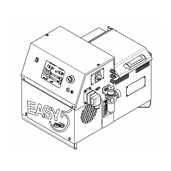
These changes may be made at any time, without PREO being bound to update this publication. With the exception of the tank capacity, the type of hoses and guns, the PREO applicator operation is the same for all models. In order to simplify the presentation of the information contained in this manual, images corresponding to model EW530E2MV, as represented in figure 1, shall be used throughout this manual. -
Page 12: Product Description
Section 2 - INTRODUCTION 2.2 PRODUCT DESCRIPTION The adhesive hot melt units described in this manual are used together with PREO hoses and guns for the composition of a hot-melt application system, as illustrated in figure 2: Figure 2 The applicator (1) melts the hot-melt adhesive and keeps it at the desired temperature. -
Page 13: Product Identification
GEAR tank capacity pump capacity 3.00 CC REV TERMO SERIES computer TRATTO SERIES CONNECTIONS channels CONNECTIONS PRESSURE CONTROL GAUGE options QUICK RELEASE VALVE HIGH TEMPERATURE VERSION © Copyright 2006 PREO SRL Edition EAW530E2MV All rights reser ved 03/2006... -
Page 14: Safety Labels
Section 2 - INTRODUCTION 2.6 SAFETY LABELS All the PREO gluing systems bear yellow labels indicating the main precautions and safety warnings to be adhered to and respected during ordinary and extraordinary use of the system. 2.7 MAIN APPLICATOR COMPONENTS... -
Page 15: Section 3
Guarantee assistance is only acknowledged if carried out by the PREO assistance service. Please contact the following assistance centres should you require any further... -
Page 16: Installation Requirements
Before installation, remove the applicator from the relative packaging. Hoses, guns and any accessories are supplied loose from the applicator and packaged in bags or boxes inside the packaging. © Copyright 2006 PREO SRL Edition EAW530E2MV All rights reser ved... -
Page 17: Applicator Assembly
Earth the entire machine correctly. In order to make the connection, you will need a suitable power cable (not supplied with the applicator). Refer to figure 8 for correct power supply connection. Figure 8 © Copyright 2006 PREO SRL Edition EAW530E2MV All rights reser ved... - Page 18 The applicators have three different power supply modes. Connect the cable on the basis of the selected voltage, as illustrated in figure 9. 380 Volt three-phase + neutral 220 Volt single-phase 220 Volt three-phase Figure 9 © Copyright 2006 PREO SRL Edition EAW530E2MV All rights reser ved 03/2006...
-
Page 19: Pneumatic Supply Connection
The recommended pressure is 6 bar. 3.8 HEATED HOSE CONNECTION Wire and plumb in the hoses to the respective connectors, as illustrated in figure 11, bearing the following aspects in mind: Figure 11 © Copyright 2006 PREO SRL Edition EAW530E2MV All rights reser ved 03/2006... -
Page 20: Gun Connection
Risk of burns. • Assemble the gun as near as possible to the substratum (5-50 mm), leaving the necessary space for carrying out maintenance work or replacing its components. © Copyright 2006 PREO SRL Edition EAW530E2MV All rights reser ved 03/2006... -
Page 21: Gun Solenoid Valve Signal Connection
Typically, the voltage is 24 V DC, but AC may also be used if necessary. 3.11 MACHINE READY SIGNAL CONNECTION Figure 14 © Copyright 2006 PREO SRL Edition EAW530E2MV All rights reser ved... -
Page 22: Rs232 Connector Connection
PC and transmit a response. The reception transmission protocol works through the transmission of a sequence of 8 consecutive bytes from the PC/PLC, arranged as illustrated in the following table: © Copyright 2006 PREO SRL Edition EAW530E2MV All rights reser ved... - Page 23 + 3 byte + byte + 5 byte + 6 byte + 7 byte) MOD 256. If the result amounts to zero (header!), it is transformed to one. © Copyright 2006 PREO SRL Edition EAW530E2MV All rights reser ved 03/2006...
- Page 24 Section 3 - INSTALLATION © Copyright 2006 PREO SRL Edition EAW530E2MV All rights reser ved 03/2006...
-
Page 25: Section 4
Always refer to the adhesive specifications indicated in the manufacturers’ technical outlines. PREO may not be held responsible for damage caused by incorrect use of the recommended parameters. Fill the tank as described and illustrated in figure 16. -
Page 26: General Operating Information
The microprocessor features simplified programming, which is easy to use thanks to a new revolutionary LCD display, as illustrated in figure 18. Figure 18 © Copyright 2006 PREO SRL Edition EAW530E2MV All rights reser ved 03/2006... -
Page 27: Description Of Components
(by simply turning the selector) but preventing them from changing the set-points. 5 Motor ON/OFF switch: switches the motor controlling the gear pump on and off. © Copyright 2006 PREO SRL Edition EAW530E2MV... -
Page 28: Integrated Functions
Press the selector briefly until SET appears on the screen then, turning the selector itself, modify the set-point temperature within a range of settable values between +2°C and +230°C. The selector also has a virtual block that prevents you from exceeding 230°C. © Copyright 2006 PREO SRL Edition EAW530E2MV All rights reser ved... -
Page 29: Setting The Gun Temperatures
Repeat the same procedure to set the temperature for gun 2. 4.9 STARTING UP THE PUMP Press the switch to position 1 in order to start up the gear pump motor, as illustrated in figure 20. Figure 20 © Copyright 2006 PREO SRL Edition EAW530E2MV All rights reser ved 03/2006... -
Page 30: Setting The Pump Revolutions
Figure 21 Precise valve calibration, together with the regulation of the number of pump revolutions, allows the system to dispense the adhesive in a precise, constant and © Copyright 2006 PREO SRL Edition EAW530E2MV All rights reser ved... -
Page 31: Setting The Economy Function
Press the selector for a few seconds in order to restore normal operation. 4.14 SWITCHING THE SYSTEM OFF Turn the main switch to position 0, as illustrated in figure 22, in order to turn the system off completely. Figure 22 © Copyright 2006 PREO SRL Edition EAW530E2MV All rights reser ved 03/2006... - Page 32 Section 4 - OPERATION © Copyright 2006 PREO SRL Edition EAW530E2MV All rights reser ved 03/2006...
-
Page 33: Section 5
Only use original PREO spare parts, which can be purchased from the company sales office. Refer to the last section in this manual for a LIST OF RECOMMENDED SPARE PARTS. -
Page 34: Glue Filter Replacement
Do not use alcohol to clean the system. 5.4 GLUE FILTER REPLACEMENT PREO applicators have a disposable glue filter for hot-melt adhesives, designed to prevent adhesive slag and carbonisation while it is being pumped from the tank. The filter (positioned inside the manifold) must be replaced on the basis of the use and technical characteristics of the adhesive used. -
Page 35: Cleaning The Melting Tank
• Let all the glue flow out and then close the valve again. All PREO applicators are made using advanced technology and avant-garde coatings. Despite this, in order to ensure a long working life, we recommend © Copyright 2006 PREO SRL... -
Page 36: Fuse Replacement
Only use Ecocleaner 96 to clean the system, since the use of other products could irreparably damage the seals. PREO recommends this product because it is completely biodegradable, chemically inert, non-toxic and does not stick to the walls of the tank, allowing for perfectly safe use of the system. -
Page 37: Safety Thermostat Replacement
Code Description Q.ty KKE1720 Low temperature version safety thermostat KKE1760 Standard version safety thermostat KKE1765 High temperature version safety thermostat © Copyright 2006 PREO SRL Edition EAW530E2MV All rights reser ved 03/2006... -
Page 38: Machine Storage
Plumbing and electric components, such as valves, solenoid valves, etc. should be dismantled and then reused if still in good condition, or reviewed and recycled if possible. The machine does not contain pollutant oils. © Copyright 2006 PREO SRL Edition EAW530E2MV All rights reser ved... -
Page 39: Section 6
O_T message: indicates an OVER TEMPERATURE situation. The message appears when the safety thermostat intervenes, stopping heating completely. © Copyright 2006 PREO SRL Edition EAW530E2MV All rights reser ved... - Page 40 Section 6 - TROUBLESHOOTING © Copyright 2006 PREO SRL Edition EAW530E2MV All rights reser ved 03/2006...
-
Page 41: Section 7
ELECTRIC CONNECTIONS PRESSURE CONTROL GAUGE options QUICK RELEASE VALVE HIGH TEMPERATURE VERSION As far as regards the system characteristics and technical specifications, refer to the following technical outlines: © Copyright 2006 PREO SRL Edition EAW530E2MV All rights reser ved 03/2006... - Page 42 14 Kg/h (varies depending on type of adhesive used) MAXIMUM PUMP CAPACITY 0.25 with reducer ratio 1:20 and variable speed controlled by vectorial inverter MOTOR SPECIFICATIONS - 5°C from set - point PUMP ENABLEMENT © Copyright 2006 PREO SRL Edition EAW530E2MV All rights reser ved 03/2006...
-
Page 43: Using The Exploded Diagrams And Parts Tables
2 – EASY SERIES MANIFOLD GROUP + VALVE + PRESSURE GAUGE 3 – EASY SERIES TANK GROUP 5 KG GEARS 4 – EASY SERIES QUICK RELEASE VALVE 5 – EASY SERIES COMPUTER BOX GROUP © Copyright 2006 PREO SRL Edition EAW530E2MV All rights reser ved... - Page 44 Joint for gear pump 3.0 cc easy series PEW1520 Gear pump group kit, easy 3.0 cc PEW1530 Gear pump plate group kit, easy 3.0 cc PEW1500 Gear pump seal kit, 3.0 cc easy series © Copyright 2006 PREO SRL Edition EAW530E2MV All rights reser ved 03/2006...
- Page 45 Section 7 – TECHNICAL OUTLINES AND SPARE PARTS PEW1000-30 GEAR PUMP MOTOR GROUP, 3.0 CC EASY SERIES © Copyright 2006 PREO SRL Edition EAW530E2MV All rights reser ved 03/2006...
- Page 46 Pressure transmitter mn series TABLE 1 MANIFOLD FILTER REFERENCE TABLE ESCRIPTION NOTES DDR1130W Complete 1.00 filter group for easy applicator DDR1131W Complete 2.00 filter group for easy applicator © Copyright 2006 PREO SRL Edition EAW530E2MV All rights reser ved 03/2006...
- Page 47 Section 7 – TECHNICAL OUTLINES AND SPARE PARTS DE1000-MV EASY SERIES MANIFOLD GROUP + VALVE + PRESSURE GAUGE © Copyright 2006 PREO SRL Edition EAW530E2MV All rights reser ved 03/2006...
- Page 48 Tank protection network easy series TABLE 2 SAFETY THERMOSTAT REFERENCE TABLE ESCRIPTION NOTES KKE1720 Low temperature version safety thermostat KKE1760 Standard version safety thermostat KKE1765 High temperature version safety thermostat © Copyright 2006 PREO SRL Edition EAW530E2MV All rights reser ved 03/2006...
- Page 49 Section 7 – TECHNICAL OUTLINES AND SPARE PARTS VE0010 EASY SERIES TANK GROUP 5 KG GEARS © Copyright 2006 PREO SRL Edition EAW530E2MV All rights reser ved 03/2006...
- Page 50 Quick release valve gate seal kit ffr1021 Quick release valve gate FFR1020 Quick release valve complete gate FFR1030 Quick release valve pin kit FFR1040 Quick release valve body kit © Copyright 2006 PREO SRL Edition EAW530E2MV All rights reser ved 03/2006...
- Page 51 Section 7 – TECHNICAL OUTLINES AND SPARE PARTS FF3000 EASY SERIES QUICK RELEASE VALVE © Copyright 2006 PREO SRL Edition EAW530E2MV All rights reser ved 03/2006...
- Page 52 Section 7 – TECHNICAL OUTLINES AND SPARE PARTS WDEAW530E2MV COMPUTER BOX GROUP EASY SERIES © Copyright 2006 PREO SRL Edition EAW530E2MV All rights reser ved 03/2006...
- Page 53 6-pole socket insert easy series KKE1175 Computer keyboard lock key complete group KKD1026 Easy computer control knob MA1000 LCD control card easy series KKE1160 Luminous green switch 10° 0/1 © Copyright 2006 PREO SRL Edition EAW530E2MV All rights reser ved 03/2006...
- Page 54 Filter regulator group ¼ bit easy ---- Filter regulator ¼ bit easy ---- Pressure gauge 0-6 bar 1/8” diam. 40 mm ---- Filter regulator ¼ bit fixture bracket © Copyright 2006 PREO SRL Edition EAW530E2MV All rights reser ved 03/2006...
- Page 56 - EAW530E2MV - - EDITION 03/2006 © Co p yr ig ht 2006 PREO SRL - All right s reserved - Subject to chang e without advanced n otice - Printed in Italy PREO SRL PREO SRL - Export Department www.preo.it...
Need help?
Do you have a question about the EASY 5 Series and is the answer not in the manual?
Questions and answers