Advertisement
Quick Links
MCS ELECTRONICS
Making Things Easy
Easy-TCP/IP
I²C / TWI interface
Reduces the use of I/O pins
(Only 4 pins needed for TCP/IP)
Cost saving, by reducing
components
I²C / TWI enables low cost
microcontrollers to interact with
the Internet
Easy-TCP/IP
I²C / TWI interface
Version
1.6
Advertisement

Subscribe to Our Youtube Channel
Summary of Contents for MCS ELECTRONICS Easy-TCP/IP
- Page 1 Version MCS ELECTRONICS Making Things Easy Easy-TCP/IP I²C / TWI interface Reduces the use of I/O pins (Only 4 pins needed for TCP/IP) Cost saving, by reducing components I²C / TWI enables low cost microcontrollers to interact with the Internet Easy-TCP/IP I²C / TWI interface...
- Page 2 M C S E L E C T R O N I C S Easy-TCP/IP I²C / TWI Interface Guide © 1995-2006 MCS Electronics www.mcselec.com 2 2 2 2...
- Page 3 T able of Contents Introduction 1. Getting started 1.1 Assembling your PCB 2. Configuring the 7010A Adapter 3 3 3 3...
- Page 4 The reduction of I/O pins of the Easy-TCP/IP TWI makes it slower than the EASY- TCP, but for a lot of embedded applications high speed is not a requirement. It’s up to you to decide whether you choose speed, Easy-TCP or a compact and economic Easy-TCP/IP TWI.
- Page 5 TCP/IP and how to configure and test the EASY-TCP/IP series in your LAN. The Easy-TCP/IP TWI board is meant to give you a way of experimenting with TCP/IP and BASCOM. If you wish to build your own complete solution we suggest you implement the NM7010A Adapter Board in your own system.
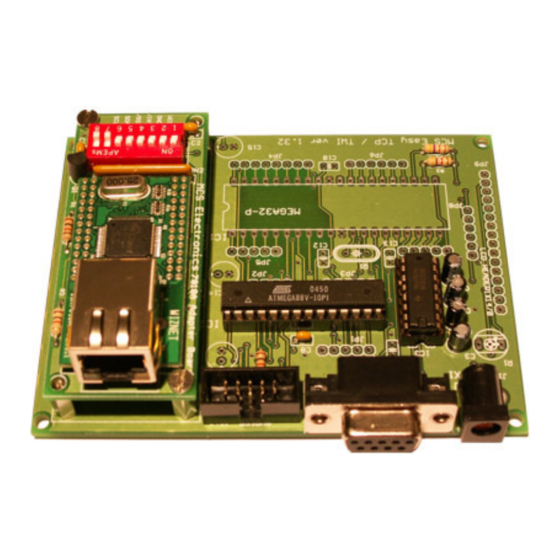
- Page 6 MOTHERBOARD LAYOUT (version 1.33) To find the right position of the components you may want to reference this drawing of the board layout. It is also printed on the PCB itself. PARTS LIST EASY-TCP/IP Motherboard (Controller) Component Description Value POTENTIOMETER . Only needed when LCD display is used.
- Page 7 C7, C14, C15 ELCO Radial 10 uF/16V CERAMIC CAPACITOR. Optional, only C12, 13 needed when you use an external oscillator. 22pF CRYSTAL . Optional. Only needed when you do not want to use the micro processor internal oscillator. 8 MHz VOLTAGE REGULATOR 5V 7805 VOLTAGE REGULATOR 3V3...
- Page 8 Since there are 2 versions of the Adapter board, we describe them both. Do not solder the ATMega’s at this time, continue soldering the 7010 Adapter board. You are not to solder the micros at all. NON-SMD Adapter board PARTS LIST EASY-TCP /IP 7010A NON-SMD Adapter Board Component Description Value...
- Page 9 SMD Adapter board PARTS LIST EASY-TCP /IP 7010A SMD Adapter Board Component Description Value R1,2 RESISTOR 1/4W SMD C1, 2 CERAMIC CAPACITOR 100 nF RESISTOR NETWORK 8 x 10kOHM Connector PIN HEADER BEWARE: SOLDER ON TOP LAYER DIP SWITCH DIP08 PNP TYPE TRANSISTOR SMD BC857 TCP/IP MODULE...
- Page 10 Tantalium elco 22uF/10V PH3, PH4 2 pin header Do not place the adapter board on the main board yet. Note 1 : The adapter board is connected to the Motherboard with a 6/7-pin male header. This header must be soldered on the board so it points downward. Solder it from the top of the board so that it can be inserted into the Motherboard female header, which will be below it.
- Page 11 The SMD-Adapter board has 7 pins. It has an on board 3V3 regulator. It can provide power to your own circuit too. Since the regulator needs an power source of 5V or more, this adapter board has an additional pin. It is named 5- 12V on the PCB.
- Page 12 Chapter 2. Configuring the 7010A Adapter This chapter explains how to configure the 7010A Adapter. he only thing that needs to be configured is the 7010A’s slave address. This can be done with DIP switch S1. The TWI/I2C slave must have a unique address. The LS bit is used to indicate Read or Write and cannot be set.
- Page 13 The “On” on the silk screen of the PCB might not match the “On” of the DIP switch. But make sure that the pin numbers of the DIP match the PIN numbers of the silk. In the example programs, address 128(dec) is used. This is &H80(hex) or 10000000(bin).
- Page 14 This is in fact the only difference between a program that uses TWI or the high speed address mode. You can now start experimenting with the EASY-TCP/IP TWI board. Make sure you keep your copy of BASCOM up to date in order to get new samples.
- Page 15 Print "Init TCP" ' display a message Enable Interrupts ' before we use config tcpip , we need to enable the interrupts Config Tcpip Int0 12.128.12.34.56.78 192.168.0.8 Submask 255.255.255.0 Gateway 0.0.0.0 Localport 1000 &H80 Clock 400000 As Byte 'for i2c test As Long ' IP number of time server As Byte...
- Page 16 The Easy TCP/TWI Motherboard uses the DTR line to control the RESET of the micro processor. This way you can use the MCS Bootloader to reset the board automatic when you update/load the program. But when you do not use the MCS Bootloader, the micro will be reset when DTR is not made low. Third party terminal emulators might also set DTR high.
- Page 17 Mother Board...
- Page 18 Adapter board...
Need help?
Do you have a question about the Easy-TCP/IP and is the answer not in the manual?
Questions and answers