Advertisement
Quick Links
CrossOver X45 Lock Installation
Need another copy of these installation sheets? You can download one at www.CrossOverLock.com/SupportCenter.htm
©
Copyright 2010, TimePilot Corporation, 340 McKee Street, Batavia, Illinois 60510 www.CrossOverLock.com
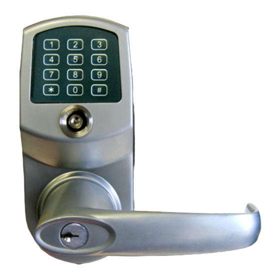
Major lock parts
1. Outside Handle
12. Mounting Plate Screws
2. Override Shaft (inside
13. Inside Catch Pin
Center Hub)
14. Mounting Screws
3. Center Hub
15. Inside Handle
4. Outside Catch Pin
16. Battery Lid Screws
5. Outside Lock Housing
17. Battery Lid
6. Square Drive Shaft
18. Inside Lock Housing
7. Latch
19. Mounting Plate Screw
8. Latch Screws
20. Mounting Plate
9. Strike Plate Screws
21. Inside Gasket
10. Strike Plate
22. Outside Gasket
11. Dust Boot
1
Advertisement

Related Manuals for TimePilot CrossOver X45

Summary of Contents for TimePilot CrossOver X45
- Page 1 16. Battery Lid Screws 5. Outside Lock Housing 17. Battery Lid 6. Square Drive Shaft 18. Inside Lock Housing 7. Latch 19. Mounting Plate Screw 8. Latch Screws 20. Mounting Plate 9. Strike Plate Screws 21. Inside Gasket 10. Strike Plate 22. Outside Gasket 11. Dust Boot © Copyright 2010, TimePilot Corporation, 340 McKee Street, Batavia, Illinois 60510 www.CrossOverLock.com...
- Page 2 Step 1: Install the latch Step 2: Install the outer half of the lock If necessary, drill holes in door as shown in the A. Place the outside gasket accompanying template. Then insert the latch into the on the back of the hole and attach it with two screws. outside half of the lock (the half with the keypad) and align the gasket along the edge of the lock. B. Insert the slightly larger end (with the hole in it) of the square drive shaft The dot on the center hub should be pointing to the left. into the center hub. Figure 2 Make sure that the dot on the center hub is pointing to the left. (Figure 2) Figure 1 C. Slide the outside half of the lock into the door, running the drive shaft through the latch and feeding the power cable above or below the latch in the door hole. (Figure 3) Figure 3 Step 4: Install the inside half of the lock Step 3: Install the inside mounting plate A. Plug the power cable into the inside half of the lock, A. Place the inside gasket on the door and align it then place the inside half on the mounting plate, with the door hole. Make sure the three nubs making sure that the square drive shaft fits into the on surface of the gasket aren’t facing the door. center hub of the lock half and that the lock half is ...
- Page 3 Step 5: Install the inside handle Step 6: Install the emergency lock cylinder and the outside handle Decide whether the inside handle—the A. Make sure the override shaft inside the center Override shaft is in a vertical position handle without a keyhole—should hub is in a vertical position. (Figure 7) Use a point to the right or left, and insert it flat‐bladed screwdriver to turn the shaft if onto the center hub, pressing in the necessary. appropriate pin on the side of the B. Remove the key from the cylinder, then place center hub so it fits into the hole on the cylinder into the outside handle, exposing the side of the handle. the cylinder’s keyhole in the hole in the handle. Insert the key into the cylinder and turn the cylinder/key assembly so that the flange on the Front view cylinder is pointing to the right and will fit into Figure 7 the slot on the right side of the center hub. (Figure 8) Flange C. If necessary, turn the key clockwise a quarter‐turn so that the black tab extending from the back of the cylinder (Figure 8) is vertical, so that it matches the override shaft in Step A. Figure 6 D. Decide whether the handle should point to the right or left (generally, the inside and outside handles point in the same direction). While guiding the cylinder into the cylinder housing, Cylinder press the handle onto the center hub, depressing the Black tab appropriate pin on the side of the hub so it fits into the hole on the side of the handle. ...
- Page 4 Notes ...
- Page 5 2 3/8 in. 3 3/8 in. 1/8 in. 2 1/4 in. 2 1/4 in. Ø 1 1/8 in. 1 1/8 in. Ø 2 1/8 in. 1 3/8 to 2 in. Copyright 2010, TimePilot Corporation, all rights reserved. www.CrossOverLock.com Product No.: IS-01025203...
- Page 6 2 3/4 in. 3 3/8 in. 1/8 in. 2 1/4 in. 2 1/4 in. Ø 1 1/8 in. 1 1/8 in. Ø 2 1/8 in. 1 3/8 to 2 in. Copyright 2010, TimePilot Corporation, all rights reserved. www.CrossOverLock.com Product No.: IS-01025203...
- Page 7 (See pages 5 and 6 for door templates) 1 9/16 in. 7/8 in. 7/16 in. 1/8 in. 1 5/8 in 1 1/8 in. 1 1/8 in. 3/8 in. Copyright 2010, TimePilot Corporation, all rights reserved. www.CrossOverLock.com Product No.: IS-01025203...
Need help?
Do you have a question about the CrossOver X45 and is the answer not in the manual?
Questions and answers