Table of Contents
Advertisement
Quick Links
Advertisement
Table of Contents

Related Manuals for Sunnytech ST2420

Summary of Contents for Sunnytech ST2420
- Page 1 ST Maximum Power Point Tracking (MPPT) Series ST2420—ST2430—ST2440 Solar Charge and Discharge Controller User Manual Model ST2420 ST2430 ST2440 Battery voltage 12V/ 24V Max. solar panel voltage 100V (25°C), 90V (-25°C) Charging current Discharging current...
- Page 2 Dear users, Thank you for choosing our product! Safety Instructions 1. As this controller deals with voltages that exceed the top limit for human safety, do not operate it before reading this manual carefully and completing safety operation training. 2. The controller has no internal components that need maintenance or service, thus do not attempt to disassemble or repair the controller.
-
Page 3: Table Of Contents
Table of Contents 1. Product Introduction........................ 4 1.1 Product Overview......................4 1.2 Product Features........................ 4 1.3 Exterior and Interfaces...................... 6 1.4 Introduction to Maximum Power Point Tracking Technology......... 7 1.5 Charging Stages Introduction.................... 9 2. Product Installation........................12 2.1 Installation Precautions....................12 2.2 Wiring Specifications...................... -
Page 4: Product Introduction
6.1 12V System Conversion Efficiency................31 6.1 24V System Conversion Efficiency................31 7. Product Dimensions.........................32 1. Product Introduction 1.1 Product Overview This product can keep monitoring the solar panel's generating power and tracking the highest voltage and current values (VI) in real time, enabling the system to charge the battery in maximum power. - Page 5 optimum working point on the I-V curve in an extremely short time. The product boasts an optimum MPPT tracking efficiency of up to 99.9%. ◆ Advanced digital power supply technologies raise the circuit's energy conversion ◆ efficiency to as high as 98%. Charging program options are available for different types of batteries includinggel ◆...
-
Page 6: Exterior And Interfaces
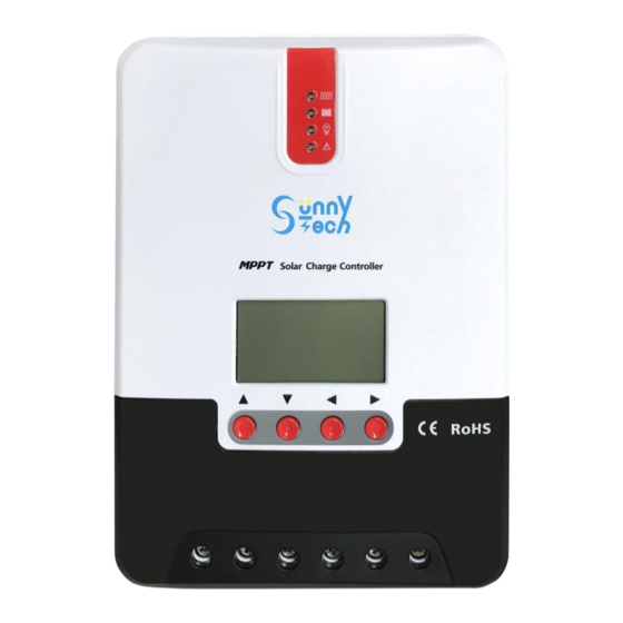
TVS lighting protection ◆ 1.3 Exterior and Interfaces ○ ○ ○ ○ ○ ○ ○ ○ Definition Transmitting terminal TX ○ Receiving terminal RX ○ Power supply grounding /Signal grounding ○ Power supply grounding /Signal grounding ○ Power supply positive ○... -
Page 7: Introduction To Maximum Power Point Tracking Technology
○ ○ Abnormality indicator Load "-" interface ○ ○ LCD screen External temperature sampling interface ○ ○ Operating keys RS232 communication interface ○ Installation hole ○ Solar panel "+" interface ○ Solar panel "-" interface 1.4 Introduction to Maximum Power Point Tracking Technology Maximum Power Point Tracking (MPPT) is an advanced charging technology that enables the solar panel to output more power by adjusting the electric module's operating status. - Page 8 VP curve VI curve MPPT point I (A) P (W) PWM charging Fig. 1-2 Solar panel output characteristic curve Meanwhile, due to changing ambient temperature and illumination conditions, the max. power point varies frequently, and our MPPT controller can adjust parameter settings according to the environmental conditions in real time, so as to always keep the system close to the max.
-
Page 9: Charging Stages Introduction
With temperature dropping, current stays stable and power increases Open-circuit voltage decreases with rising temperature Fig. 1-4 Relation between solar panel output characteristics and temperature 1.5 Charging Stages Introduction As one of the charging stages, MPPT can not be used alone, but has to be used together with boost charging, floating charging, equalizing charging, etc. - Page 10 Time Fig. 1-5 Battery charging stages diagram a) Fast charging At the fast charging stage, as the battery voltage has not reached the set value of full voltage (i.e. equalizing/ boost When the voltage) yet, the controller will perform MPPT charging on the battery with the maximum solar power. battery voltage reaches the preset value, constant voltage charging will begin.
- Page 11 of duration and boost voltage point according to the actual needs. When the duration reaches the set value, the system will then switch to floating charging. Equalizing charging Warning: risk of explosion! In equalizing charging, an open lead-acid battery can produce explosive gas, therefore the battery chamber shall have good ventilation conditions.
-
Page 12: Product Installation
continuously stabilize the battery voltage to a constant level, the controller will initiate a timing process, and 3 hours after the battery voltage reaches the set value, the system will automatically switch to equalizing charging. 2) If no calibration has been done to the controller clock, the controller will perform equalizing charging regularly according to its internal clock. -
Page 13: Wiring Specifications
The wiring specifications of the battery and loads must be selected according to rated currents, and see the following table for wiring specifications: Model Rated Rated Battery wire Load wire charging discharging diameter diameter current current (mm2) (mm2) ST2420 ST2430 ST2440... -
Page 14: Installation And Wiring
2.3 Installation and Wiring Warning: risk of explosion! Never install the controller and an open battery in the same enclosed space! Nor shall the controller be installed in an enclosed space where battery gas may accumulate. Warning: danger of high voltage! Photovoltaic arrays may produce a very high open-circuit voltage. - Page 15 Step 1: choose the installation site Do not install the controller at a place that is subject to direct sunlight, high temperature or water intrusion, and make sure the ambient environment is well ventilated. Step 2: first place the installation guide plate at a proper position, use a marking pen to mark the mounting points, then drill 4 mounting holes at the 4 marked points, and fit screws in.
- Page 16 Step 4: wire First remove the two screws on the controller, and then begin wiring operation. In order to guarantee installation safety, we recommend the following wiring order; however, you can choose not to follow this order and no damage will be incurred to the controller. Connecting to external temperature sampling interface ○...
- Page 17 Warning: risk of electric shock! We strongly recommend that fuses or breakers be connected at the photovoltaic array side, load side and battery side so as to avoid electric shock during wiring operation or faulty operations, and make sure the fuses and breakers are in open state before wiring.
-
Page 18: Product Operation And Display
Warning: within 10 minutes after the controllers stops charging, if the battery's poles are reversely connected, internal components of the controller may get damaged. Note: 1) The battery's fuse or breaker shall be installed as close to the battery sideas possible, and it's recommended that installation distance be not more than 150mm. - Page 19 state Steady on MPPT ○ charging Slow flashing ○ Boost (a cycle of 2s with on and off charging each lasting for 1s) Single flashing ○ (a cycle of 2s with on and off Floating lasting respectively for 0.1s and charging 1.9s) Quick flashing...
- Page 20 Quick flashing Battery over-voltage (a cycle of 0.2s with on and off each lasting for 0.1s) LOAD indicator: Indicator state Load state Load turned off Quick flashing Load overloaded/ (a cycle of 0.2s with on and off short-circuited each lasting for 0.1s) Steady on Load functioning normally...
-
Page 21: Key Operations
3.2 Key Operations Page up; increase the parameter value in ▲ setting Page down; decrease the parameter value in ▼ Down setting Return to previous menu (exit without ◄ Return saving) Enter into sub-menu; set/ save ► Turn on/ off loads (in manual mode) 3.3 LCD Startup and Main Interface Parameter value Nighttime Daytime Solar panel... - Page 22 During startup, the 4 indicators will first flash successively, and after self- inspection, the LCD screen starts and displays the battery's voltage level which will be either a fixed voltage selected by the user or a voltage automatically recognized. 3.3.2 Main interface...
-
Page 23: Load Mode Setting Interface
Main monitoring page Charging current Component voltage Battery voltage Battery capacity Abnormality code Charging capacity Load current Device temperature Load mode Discharging capacity 3.4 Load Mode Setting Interface 3.4.1 Load modes introduction This controller has 5 load operating modes which will be described below: Mode Descriptions When no sunlight is present, the solar panel voltage is lower than the light control on... -
Page 24: System Parameter Settings
signals, the load is switched on. This mode enables fast check of the correctness of system installation during installation debugging. The energized load keeps outputting, and this mode is suitable for loads which need Normal on mode 24-hour power supply. 3.4.2 Load mode adjustment Users can adjust the load mode as needed on their own, and the default mode is debugging mode (see "load modes introduction"). -
Page 25: Product Protection Function And System Maintenance
Note: after system voltage setting, power supply has to be switch off and then on again, otherwise the system may work under an abnormal system voltage. The controller enables users to customize the parameters according to the actual conditions, but parameter setting must be done under the guidance of a professional person, or else faulty parameter settings may render the system not able to function normally. - Page 26 from damaging the controller and enter into current-limited charging. Battery reverse connection protection If the battery is reversely connected, the system will simply not operate so as to protect the controller from being burned. Photovoltaic input side too high voltage protection If the voltage on the photovoltaic array input side is too high, the controller will automatically cut off photovoltaic input.
-
Page 27: System Maintenance
power or halt charging. See the following diagram: Fig. 4-1 4.2 System Maintenance In order to always keep the controller's performance at its optimum level, we ◆ recommend that the following items be checked twice a year. Make sure the airflow around the controller is not blocked and clear away any dirt ◆... -
Page 28: Abnormality Display And Warnings
operations, always make sure all power supplies of the controller have been cut off! 4.3 Abnormality Display and Warnings Error display Description LED indication ERROR indicator No abnormality BAT indicator flashing slowly Battery over-discharge ERROR indicator steady on BAT indicator System flashing quickly ERROR indicator... -
Page 29: Battery Type Default Parameters (Parameters Set In Monitor Software)
Model ST2420 ST2430 ST2440 System voltage 12V/24V Auto No-load loss 0.7 W to 1.2W Battery voltage 9 to 35 Max. solar input voltage 100V (25°C), 90V (-25°C) Max. power point voltage Battery voltage +2V to 75V range Rated charging current Rated load current Max. - Page 30 Under-voltage warning 12.2V 12.2V 12.2V 9 to 17V return voltage Under-voltage warning 12.0V 12.0V 12.0V 9 to 17V voltage Low-voltage cut-off voltage 11.1V 11.1V 11.1V 9 to 17V Discharging limit voltage 10.6V 10.6V 10.6V 9 to 17V Over-discharge time delay 1 to 30s Equalizing charging 120 minutes...
-
Page 31: Conversion Efficiency Curve
6. Conversion Efficiency Curve 6.1 12V System Conversion Efficiency MPPT 12V conversion efficiency (12V battery) Output power(W) 6.1 24V System Conversion Efficiency MPPT 24V conversion efficiency (24V battery) Output power(W)... - Page 32 7. Product Dimensions ST2440 Product dimensions Hole positions Hole diameter Applicable wire: max. 8 AWG Product dimensions Hole positions Hole diameter Applicable wire: max. 8 AWG...
Need help?
Do you have a question about the ST2420 and is the answer not in the manual?
Questions and answers