Table of Contents
Advertisement
Quick Links
Advertisement
Table of Contents

Summary of Contents for Micronica HiP-400
- Page 1 User Manual U-011-03E0-000516...
- Page 2 Copyright The contents of this publication may not be reproduced in any part or as a whole, stored, transcribed in an information retrieval system, translated into any language, or transmitted in any form or by any means, mechanical, magnetic, electronic, optical, photocopying, manual, or otherwise, without the prior written permission.
- Page 3 FCC Interference Statement This equipment has been tested and found to comply with the limits for a Class B digital device pursuant to Part 15 of the FCC Rules. T hese limits are designed to provide reasonable protection against radio interference in a commercial environment. This equipment can generate, use and radiate radio frequency energy and, if not installed and used in accordance with the instructions in this manual, may cause harmful interference to radio communications.
-
Page 4: Table Of Contents
Table of Contents Chapter 1 Introduction................5 1.1 Functions and Features ..............5 1.2 Packing List..................6 Chapter 2 Hardware Installation..............7 2.1. Panel Layout..................7 2.2. Installation Requirements ..............8 2.3. Procedure for Hardware Installation..........8 Chapter 3 Network Settings and Software Installation ......11 3.1 Make correct network settings of your computer......11 3.2 Install the Software into Your Computers ........12 Chapter 4 Configuring IP Sharer .............15 4.1 Start-up and Log in...............15... - Page 5 Appendix B TCP/IP Configuration for Windows 95/98 ......30 B.1 Install TCP/IP protocol into your PC...........30 B.2 Set TCP/IP protocol for working with IP Sharer......31...
-
Page 6: Chapter 1 Introduction
Chapter 1 Introduction Congratulations on your purchase of this outstanding Broadband Router. This product is specifically designed for Small Office and Home Office needs. It provides a complete SOHO solution for Internet surfing and office resources sharing, and it is easy to configure and operate for even non-technical users. -
Page 7: Packing List
Web-based configuring configurable through any networked computer’s web browser using Netscape or Internet Explorer. Access Control supported allows you to assign different access right for different users. Virtual Server supported enables you to expose WWW, FTP and other services on your LAN to be accessible to Internet users. -
Page 8: Chapter 2 Hardware Installation
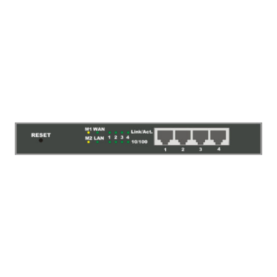
Chapter 2 Hardware Installation 2.1. Panel Layout 2.1.1. Front Panel Figure 2-1 Front Panel RESET When RESET is pushed, system settings will be set to factory defaults. M1&M2 System status indicators, Orange. M1 is flashed once per second to indicate system is alive. When system is busy, M2 is lighted. WAN &... -
Page 9: Installation Requirements
Serial port connector (9-pins D-type male). This is where you will connect your modem. This port is also a console port. Power Power inlet. This is where you connect the included power adapter. Note that, the included power adapter is DC 5V/1A. Using wrong type of power adapter may cause this product damage. - Page 10 Figure 2-5 Setup of LAN connections for this product. 2. Setup WAN connection: prepare an Ethernet cable for connecting this product to your cable/xDSL modem or Ethernet backbone. Figure 2-5 illustrates the WAN connection. 3. Connecting this product with your printer: use the printer cable to connect your printer to the printer port of this product.(Optional) Figure 2-6 Setup of WAN and Printer connections for this product.
- Page 11 the indicators M1 and M2 will be lighted ON for about 5 seconds, and then M1 and M2 will be flashed 3 times to indicate that the self-test operation has finished. Finally, the M1 will be continuously flashed once per second to indicate that this product is in normal operation.
-
Page 12: Chapter 3 Network Settings And Software Installation
Chapter 3 Network Settings and Software Installation To use this product correctly, you have to properly configure the network settings of your computers and install the attached setup program into your MS Windows platform (Windows 95/98/NT). 3.1 Make correct network settings of your computer The default IP address of this product is 192.168.123.254, and the default subnet mask is 255.255.255.0. -
Page 13: Install The Software Into Your Computers
there must be something wrong in your installation procedure. You have to check the following items in sequence: Is the Ethernet cable correctly connected between this product and your computer? Tip: The LAN LED of this product and the link LED of network card on your computer must be lighted. - Page 14 Step 2: Click on the INSTALL button. Wait until the following Welcome dialog to appear, and click on the Next button. Step 3: Select the destination folder and click on the Next button. Then, the setup program will begin to install the programs into the destination folder. -13-...
- Page 15 Step 4: When the following window is displayed, click on the Finish button. Step 5: Select the item to restart the computer and then click the OK button to reboot your computer. Step 6: After rebooting your computer, the software installation procedure is finished. Now, you can configure the Internet Sharer (refer to Chapter 4) and setup the Print Server (refer to Chapter 5).
-
Page 16: Chapter 4 Configuring Ip Sharer
Chapter 4 Configuring IP Sharer This product provides Web based configuration scheme, that is, configuring by Netscape Communicator or Internet Explorer. This approach can be adopted in any MS Windows, Macintosh or UNIX based platforms. 4.1 Start-up and Log in Activate your browser, and disable the proxy or add the IP address of this product into the exceptions. -
Page 17: Status
web appearance will be changed into administrator configure mode. As listed in its main menu, there are several options for system administration. 4.2 Status This option provides the function for observing this product’s working status: A. WAN Port Status. If the WAN port is assigned a dynamic IP, there may appear a “Renew” or “Release”... -
Page 18: Toolbox
4.3 Toolbox This option enables you change the administrator password. Besides, you can get the information about Firmware version and WAN's MAC Address. You can also reboot this product by clicking the Reboot button. Note: we strongly recommend you to change the system password for security reason. If you forgot the system password, please refer to Appendix A to reset a new one. -
Page 19: Primary Setup
4.4 Primary Setup This option is primary to enable this product to work properly. The setting items and the web appearance depend on the WAN type. Choose correct WAN type before you start. 1. LAN IP Address: this product’s IP address. The default address is 192.168.123.254. You can change it on your need. - Page 20 4.4.1 Static IP Address WAN IP Address, Subnet Mask, Gateway, Primary and Secondary DNS: enter the proper setting value provided by your ISP. 4.4.2 Dynamic IP Address Host Name: optional. Required by some ISPs, for example, @Home. Renew IP Forever: this feature enable this product renew IP address automatically when the lease time is being expired even the system is in idle state.
-
Page 21: Dhcp Server
4.5 DHCP Server The settings of TCP/IP environment include Host IP, Subnet Mask, Gateway, and DNS configurations. It is not a simple task to correctly configure all the computers in your LAN environment. Fortunately, DHCP provides a rather simple approach to handle all these settings. -
Page 22: Virtual Server
4.6 Virtual Server This product’s NAT firewall filters out unrecognized packets to protect your Intranet, so all hosts behind this product are invisible to the outside world. If you wish, you can make some of them accessible by enabling the Virtual Server Mapping. A virtual server is defined as a Service Port, and all requests to this port will be redirected to the computer specified by the Server IP. -
Page 23: Special Ap
4.7 Special AP Some applications require multiple connections, like Internet games, Video conferencing, Internet telephony and so on. Due to the firewall function, these applications can not work with pure NAT router. Special Applications makes some of these applications to work with NAT router. -
Page 24: Access Control
4.8 Access Control Access Control allows you to assign different access right for different users. First, you have to divide users into different groups. Users are identified by their IP addresses. You can assign the members of Group 1, 2 and 3. The others are all members of Default Group. Second, you have to assign the access right of each group. -
Page 25: Misc Items
4.9 Misc Items 1. IP Address of DMZ Host: DMZ (DeMilitarized Zone) Host is a host without the protection of firewall. It allows a computer to be exposed to unrestricted 2-way communication. Note that, this feature should be used only when needed. 2. -
Page 26: Chapter 5 Print Server
Chapter 5 Print Server This product provides the function of network print server for MS Windows 95/98/NT and Unix based platforms. (If the product you purchased doesn’t have printer port, please skip this chapter.) 5.1 Configuring on Windows 95/98 Platforms After you finished the software installation procedure described in Chapter 3, your computer has possessed the network printing facility provided by this product. - Page 27 1. Find out the corresponding icon of your s erver printer, for example, the HP LaserJet 6L. Click the mouse’s right button on that icon, and then select the Properties item: 2. Click the Details item: -26-...
-
Page 28: Configuring On Windows Nt Platforms
3. Choose the “PRTmate: (All-in-1)” from the list attached at the Print To item. Be sure that the Printer Driver item is configured to the correct driver of your server printer. 4. Click on the button of Port Settings: Type in the IP address of this product and then click the OK button. 5. -
Page 29: Configuring On Unix Based Platforms
Compared to the procedure in last section, the selection of Details is equivalent to the selection of Ports, and Port Settings is equivalent to Configure Port. 5.3 Configuring on Unix based Platforms Please follow the traditional configuration procedure on Unix platforms to setup the print server of this product. -
Page 30: Appendix A Console Mode
Appendix A Console Mode When you forget the system password or the IP address of this product, you need enter console mode to reset them. Before invoking the console program, be sure to find a null modem cable and use it to connect from this product’s COM port to your computer’s COM port. - Page 31 Appendix B TCP/IP Configuration for Windows 95/98 This section introduces you how to install TCP/IP protocol into your personal computer. And suppose you have been successfully installed one network card on your personal computer. If not, please refer to your network card manual. Moreover, the Section B.2 tells you how to set TCP/IP values for working with this IP Sharer correctly.
- Page 32 5. Select Microsoft item in the manufactures list. And choose TCP/IP in the Network Protocols. Click OK button to return to Network window. 6. The TCP/IP protocol shall be listed in the Network window. Click OK to complete the install procedure and restart your PC to enable the TCP/IP protocol. B.2 Set TCP/IP protocol for working with IP Sharer 1.
- Page 33 2. Double click Network icon. Select the TCP/IP line that has been associated to your network card in the Configuration tab of the Network window. 3. Click Properties button to set the TCP/IP protocol for this IP Sharer. 4. Now, you have two setting methods: A.
- Page 34 Select Obtain an IP address automatically in the IP Address tab. b. Don’t input any value in the Gateway tab. -33-...
- Page 35 c. Choose Disable DNS in the DNS Configuration tab. -34-...
- Page 36 B. Configure IP manually Select Specify an IP address in the IP Address tab. The default IP address of this product is 192.168.123.254. So please use 192.168.123.xxx (xxx is between 1 and 253) for IP Address field and 255.255.255.0 for Subnet Mask field.
- Page 37 b. In the Gateway tab, add the IP address of this product (default IP is 192.168.123.254) in the New gateway field and click Add button. c. In the DNS Configuration tab, add the DNS values which are provided by the ISP into DNS Server Search Order field and click Add button. -36-...
Need help?
Do you have a question about the HiP-400 and is the answer not in the manual?
Questions and answers