Table of Contents
Advertisement
Quick Links
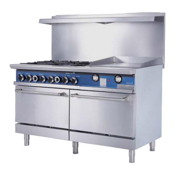
INSTALLATION & OPERATION MANUAL
GAS RESTAURANT RANGES
Models: CP-R24, CP-R36, CP-R60, CP-R60-24MG
CP-R60-24TG, CP-R60-24CB
WARNING: IMPROPER INSTALLATION, ADJUSTMENT, ALTERATION, SERVICE OR MAINTENANCE CAN
CAUSE PROPERTY DAMAGE, INJURY OR DEATH. READ THE INSTALLATION, OPERATING AND MAINTENANCE
INSTRUCTIONS THOROUGHLY BEFORE INSTALLING OR SERVICING THIS EQUIPMENT.
1
Advertisement
Table of Contents

Summary of Contents for CORE PRO COOKING CP-R2
- Page 1 INSTALLATION & OPERATION MANUAL GAS RESTAURANT RANGES Models: CP-R24, CP-R36, CP-R60, CP-R60-24MG CP-R60-24TG, CP-R60-24CB WARNING: IMPROPER INSTALLATION, ADJUSTMENT, ALTERATION, SERVICE OR MAINTENANCE CAN CAUSE PROPERTY DAMAGE, INJURY OR DEATH. READ THE INSTALLATION, OPERATING AND MAINTENANCE INSTRUCTIONS THOROUGHLY BEFORE INSTALLING OR SERVICING THIS EQUIPMENT.
-
Page 2: Important For Your Safety
IMPORTANT FOR YOUR SAFETY THIS MANUAL HAS BEEN PREPARED FOR PERSONNEL QUALIFIED TO INSTALL GAS EQUIPMENT, WHO SHOULD PERFORM THE INITIAL FIELD START-UP AND ADJUSTMENTS OF THE EQUIPMENT COVERED BY THIS MANUAL. POST IN A PROMINENT LOCATION THE INSTRUCTIONS TO BE FOLLOWED IN THE EVENT THE SMELL OF GAS IS DETECTED. - Page 3 Model List view Total Input Shipping Crated Model No. Descriptio View Width BTU/hr Dimensions Weight Lbs/Kgs 4 top 153,000/NG burner W27.5 X 136,000/LP 366 / 166 CP-R24 range, one 24” D36.6X H42.3 24” oven 6 top 213,000/NG W39.5 X burner 190,000/LP 471 / 214 D36.6X H42.3...
- Page 4 Orifice size & BTU BTU per Orifice Description Pressure burner size 5"(NAT)-24”36” / 6"(NAT)-60” 30,000 Top burner 10"(LP) 27,000 5"(NAT)-24”36” / 6"(NAT)-60” 33,000 Oven 10"(LP) 28,000 5"(NAT)-24”36” / 6"(NAT)-60” 30,000 Top griddle 10"(LP) 27,000 5"(NAT)-24”36” / 6"(NAT)-60” 30,000 thermostat 10"(LP) 27,000 griddle 5"(NAT)-24”36”...
-
Page 5: Installation Codes And Standards
INSTALLATION UNCRATING This range was inspected before leaving the factory. The transportation company assumes full responsibility for safe delivery upon acceptance of the shipment. Immediately after unpacking, check for possible shipping damage. If the range is found to be damaged, save the packaging material and contact the carrier within 15 days of delivery. - Page 6 Ranges must be installed in accordance with: In the United States of America: 1. State and local codes. 2. National Fuel Gas Code, ANSI/Z223.1 (latest edition). Copies may be obtained from The American Gas Association, Inc., 1515 Wilson Blvd., Arlington, VA22209. In Canada: 1.
- Page 7 Reconnect this restraint prior to turning the gas supply on and returning the range to its installation position. Separate instructions for installing casters to the range are included with the casters. Note: If the range is installed on casters and is moved for any reason, it is recommended that the range be leveled front to back and side to side.
- Page 8 shelf. Remove the backsplash components from the crating materials. Assemble the required components as shown in Fig’s. 2 and 3 and 4. Fig. 2 3. Tighten the four screws to secure the shelf. Fig. 3 Fig. 4 Lift the assembly up, sliding the channels into the space provided at the rear of the range.(Fig’s.
- Page 9 Fig. 5 5. Install four #10 sheet metal screws (2 to each channel leg) (Fig. 6). Fig.6 LEVELING Check the leveling of the range. Place a level inside the oven cavity across the...
-
Page 10: Gas Connections
oven rack(s). Level front-to-back and side-to-side. To adjust the leveling, tilt the range to one side and, using channel locks, unscrew the adjustable leg insert as required. Repeat this procedure as necessary for each leg. Optional casters for this range are of the non-adjustable type. Therefore, the floor must be level. -
Page 11: Testing The Gas Supply System
Fig. 7 The arrow on the regulator shows the direction of the gas flow. The pressure regulator must be mounted horizontally to ensure proper preset outlet pressure. If the regulator is installed in any other position, the outlet pressure must be reset for proper operation. -
Page 12: Operation
When gas supply pressure exceeds psig (3.45 kPa), the range and its individual shutoff valve must be disconnected from the gas supply piping system. When gas supply pressure is 1/ psig(3.45kPa) or less, the range should be isolated from the gas supply system by closing its individual manual shutoff valve until the range is ready for start-up. -
Page 13: Before First Use
CONTROLS THERMOSTAT DIAL Allows operator to regulate oven temperature from low to 500° F (260° C) (OPTIONAL) GRIDDLE BURNER KNOB Regulates gas flow to the griddle. To increase heat, turn knob counterclockwise, to decrease heat, turn knob clockwise. BEFORE FIRST USE optional models Griddle Seasoning ( CAUTION: This griddle plate is steel, but the surface is relatively soft and can be scored... - Page 14 1. Turn main gas supply ON. Wait 30 seconds and, using a long lighter, light the hot top or griddle top pilot 3. If pilot fails to light, turn main gas supply OFF. Wait 5 minutes and repeat the above procedures. 4.
- Page 15 4. Press and hold red pilot button while lighting pilot. Once pilot is lit hold button for 30 seconds. 5. Release button. Pilot should remain on. 6. Close door. 7. If pilot fails to light, turn main gas supply OFF. Wait 5 minutes and repeat the above procedures.
- Page 16 Complete Shutdown 1. Turn burner valve OFF; pilot will remain lit. 2. Turn main gas supply OFF. optional models GRIDDLE ( 1. Turn main gas supply ON. Wait 30 seconds and, using a taper, light broiler/griddle pilot. 2. If pilot fails to light, turn main gas supply OFF. Wait 5 minutes and repeat Steps 1 and 2.
-
Page 17: Rack Arrangement -Standard Oven
1. Turn burner valve OFF; pilot will remain lit. Complete Shutdown 1. Turn burner valve OFF; pilot will remain lit. 2. Turn main gas supply OFF. STANDARD OVEN LIGHTING AND SHUTDOWN INSTRUCTIONS NOTE: Light open top/griddle pilots before lighting oven pilot. 1. -
Page 18: Maintenance
into place To remove rack, reverse the procedure above by raising rear of oven rack stop above runner and pulling rack forward. PREHEATING Standard Oven Turn thermostat control to the desired cooking temperature and preheat oven for 25 minutes. To save on gas consumption, do not operate oven at maximum heat when it is not necessary. - Page 19 When calling for service, the following information must be available: model number, serial number, manufacture date (MD) and voltage (optional models). CORE PRO GAS RESTAURANT RANGES We all recognize, however, that replacement parts and occasional professional service may be necessary to extend the useful life of this unit. When service is needed, contact a RANGE Authorized Service Agency, or your dealer.
- Page 20 36” Range parts Part Number Q’ty Description FS-302250151 Grate for hotplate FS-302250034 Burner for hotplate FS-302150041 #41 Natural orifice, hotplate FS-302150042 #53 LP orifice,hotplate Brass reducing nipple for Range Oven FS-302220059 Manual gas valve A18 FS-302220027 Pilot Valve AP6 , for Hotplate FS-03B00050 Oven thermostat FS-03600125...
- Page 21 36”Range parts Part Number Q’ty Description 6B back splash FS-100105 Shelf board Front table Knob FS-301110405 Oven thermostat knob FS-03900267 Oven door FS-100103 Oven door hinge Oven radiant plate FS-4000391 Caster set for 36"range FS-2660002 Chimney pillar support beam Front panel for 6B range FS-20228062002 Mylar for 6B range FS-303123917...
-
Page 22: Troubleshooting Guide
TROUBLESHOOTING GUIDE STANDARD OVEN RESTAURANT RANGE OVEN PROBLEM CAUSES Too much bottom heat a) Insufficient ventilation b) Improper fluing 1a. Too low temperature c) Improper thermostat bypass setting 1b. Side burning d) Thermostat out of calibration 1c. Too much top heat e) Fluctuating gas pressure a) Not level side to side 2. - Page 23 Limited Warranty Products warrants to the original owner/user that any unit manufactured by Products (“the products”) shall be free of defects in material or workmanship under normal and proper use and maintenance service as specified by Products and upon proper installation (not to exceed 120 days from date of original shipment) and start-up in accordance with the instruction manual supplied with the Product.
- Page 24 Conversion Kit Instructions for the Gas restaurant ranges CP-R24, CP-R36, CP-R60, CP-R60-24MG Models: CP-R60-24TG, CP-R60-24CB WARNING This conversion kit shall be installed by a qualified service agency in accordance with the manufacturer’s instructions and all applicable codes and requirements of the authority having jurisdiction.
- Page 25 6. Replace the orifice, burner and grate Note: Unit Number on side of orifice fittings 7. Remove the drop pan, unscrew nut of oven burner 8 .Incline the burner, expose orifice of oven 9. Replace the orifice fittings into the valve. 10, Screw out oven burner air shutter screw 11, Adjust oven burner air shutter from half open...
- Page 26 Pictured is the plastic insert. Pull off insert from octagon cap and reverse the plastic insert position so that the L.P. position is L.P. Position of attached to the octagon cap head. insert. Regulator is now converted to L.P. 13.2, Regulator convert for 60”range change the part from R500 Nat 3”-6”W.C to R500 LP 11”W.C.
Need help?
Do you have a question about the CP-R2 and is the answer not in the manual?
Questions and answers