Table of Contents
Advertisement
Quick Links
Advertisement
Table of Contents

Summary of Contents for machine technologies MP-25
- Page 1 MP-25 User Manual 60010120 ASSY, MP 25-SO - SINGLE PHASE 220V 60010121 ASSY, MP 25-HO - 3 PHASE - 220V 60010122 ASSY, MP 25-SO - 3 PHASE - 220V Revision - – 10/03/2008 620 County Road 4841, Haslet, TX 76052 Ph 817.439.1108...
- Page 2 Dear Customer, Before starting this machine please complete the following; Machine Date of purchase………………………………….. Machine serial number……………………………………… Please read the following information contained within this manual and fully familiarize yourself with the equipment. Page 2...
-
Page 3: Table Of Contents
R8-1.5 STATOR-ADJ-BLACK-INTCLAMP\ ............12 30000046 R8-1.5 ROTOR ......................12 Pump adapters ............................13 44010257- ADAPTER,PUMP 90MM-MP-25 ..................13 44010258 - ADAPTER,PUMP 113.5MM-MP-25 ................. 13 Water plate assemblies ..........................14 60010136 ASSY,WATER CONTROL MP-25-4GPM ..............14 60010142 ASSY,WATER CONTROL MP-25-7GPM ..............15 Motor mount ............................... -
Page 4: Section 1 - General Safety Information
The MP-25 mixing pump unit can produce high pressures, high torques and can use high voltages. Care must be taken by all users. Only authorized and trained persons should work with this machine. -
Page 5: Section 2 - Machine Description
Section 2 - Machine Description Function The MP-25 is a mixing pump. The machine has a drive motor, that turns a drive shaft within a material hopper that in turn feeds material through a mixing / hydration chamber to a progressive cavity rotor stator pump unit that delivers the material from the hopper to the dispense head or otherwise via a material hose / hoses. -
Page 6: Machine Illustrations
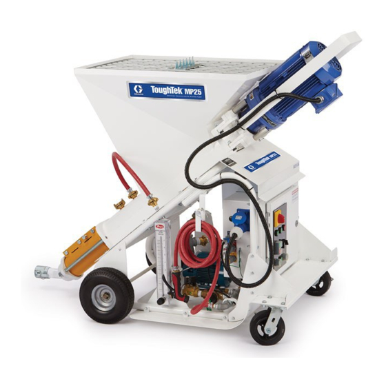
Machine illustrations Photographs Single phase, STD output, unit shown Page 6... -
Page 7: Illustration - 60010120 Assy, Mp 25-So - Single Phase 220V
Illustration – 60010120 ASSY, MP 25-SO - SINGLE PHASE 220V Page 7... -
Page 8: Bill Of Materials - 60010120 Assy, Mp 25-So - Single Phase 220V
Bill of Materials – 60010120 ASSY, MP 25-SO - SINGLE PHASE 220V Page 8... -
Page 9: Illustration - 60010121 Assy, Mp 25-Ho - 3 Phase - 220V
Illustration – 60010121 ASSY, MP 25-HO - 3 PHASE - 220V Page 9... -
Page 10: Bill Of Materials - 60010121 Assy, Mp 25-Ho - 3 Phase - 220V
Bill of Materials – 60010121 ASSY, MP 25-HO - 3 PHASE - 220V Page 10... -
Page 11: Photographs Of
Photographs of 30000039 D8-1.5 STATOR-ADJ-GREEN-INTCLAMP 30000040 D8-1.5 ROTOR 30000041 D6-3 STATOR-FIXED-ORANGE 30000042 D6-3 ROTOR Page 11... -
Page 12: 30000043 D4-3 Stator-Fixed-Green
30000043 D4-3 STATOR-FIXED-GREEN 30000044 D4-3 ROTOR 30000045 R8-1.5 STATOR-ADJ-BLACK-INTCLAMP\ 30000046 R8-1.5 ROTOR Page 12... -
Page 13: Pump Adapters
Pump adapters 44010257- ADAPTER,PUMP 90MM-MP-25 (to suit “D” series rotors and stators) 44010258 - ADAPTER,PUMP 113.5MM-MP-25 (to suit “R” series rotors and stators) Page 13... -
Page 14: Water Plate Assemblies
Water plate assemblies 60010136 ASSY,WATER CONTROL MP-25-4GPM Page 14... -
Page 15: 60010142 Assy,Water Control Mp-25-7Gpm
60010142 ASSY,WATER CONTROL MP-25-7GPM Page 15... -
Page 16: Motor Mount
Motor mount 60010134 ASSY,UPPER MTR MNT MP-25 Page 16... -
Page 17: Mixing Shaft Complete, And Clean Out Shaft Complete
Mixing shaft complete, and clean out shaft complete 60010125 ASSY, DRIVE/MIX SHAFT MP-25 Page 17... -
Page 18: 60010126 Assy, Shaft Clean Out-Mp-25
60010126 ASSY, SHAFT CLEAN OUT-MP-25 Page 18... -
Page 19: Water Pressure Tester, Water Hoses And Fan Duct
Water pressure tester, water hoses and fan duct 60010140 TESTER,WATER PRESS - 35MM-MALE-600PSI 60010139 ASSY WATER HOSE-COMPLETE-MP-25 Page 19... -
Page 20: 60010147 Assy,Pump Hose Complete Mp-25
60010147 ASSY,PUMP HOSE COMPLETE MP-25 Page 20... -
Page 21: 60010144 Assy,Fan Duct Mp-25
60010144 ASSY,FAN DUCT MP-25 60010148 ASSY,WASHDOWN HOSE COMPLETE MP-25 Page 21... -
Page 22: Electric Drive Unit
Electric Drive unit Typical layout Shown in cutaway view of upper motor mount. Unit must be greased on a daily / job-by- job basis. Page 22... -
Page 23: Cutaway View Of Seal, Dowel, Adapter And Shaft Arrangement
Cutaway view of seal, dowel, adapter and shaft arrangement Showing relationship between grooves in adaptor and seal, to allow grease to flow Page 23... -
Page 24: Electronic Drive Module - 20000046 / 47
3 Phase gear motor. The inverter unit is rated at 7.5 HP providing plenty of power to run the MP-25 unit. The module is supplied with an input plug allowing immediate wiring into your own 220VAC 2 phase or 3 Phase (as applicable depending up on the model) supply (Must be carried out by an approved installer). - Page 25 Single-phase drive module The Single-phase drive module, in addition to the previously mentioned items is equipped with an inverter error signal light, which illuminates if the inverter goes into overload for example. The three phase unit has a phase detection module with prevents the power from coming on unless the phases are wired to run the unit in the correct direction.
-
Page 26: Illustrations
Illustrations 20000046 – 3 phase Page 26... - Page 27 20000047 – single phase Page 27...
- Page 28 With cowl Page 28...
-
Page 29: Section 3 - Transportation And Positioning
Section 3 – Transportation and positioning The machine is typically manually transported around the job site using the two swivel casters at the rear of the machine to steer, with the larger wheels at the front. The machine can be picked up using a forklift, by simply inserting the forks under the base from the rear, and ensuring that they are close enough together to prevent damage to the casters. - Page 30 Care must be taken when transporting the machine due to the minimal clearance between the output connector of the pump and the ground. As the unit is “pushed” the pump connector is the furthermost pint of the machine and thus prone to damage from impact with objects in front of the machine or from the ground itself.
-
Page 31: Section 4 - Machine Set Up
Section 4 – Machine set up Unpacking Remove the safety grid from the top of the machine by removing the 4 bolts, clips and washers, using the provided 7/16” AF wrench . Keep all parts to be used to replace the grid later. -
Page 32: Machine Assembly
Machine assembly Ensure that the drive shaft is fully engaged in the rotor at the pumping end of the machine. It is essential that the round center guide be in the pilot hole of the rotor and that the lower spar be in the slot. Page 32... - Page 33 Rotate the motor output shaft and auger drive by hand, or a suitable lever until the flat end of the mixing shaft aligns with the slot in the end of the hauling bracket on the motor. Page 33...
- Page 34 swing the motor assembly into position, checking that the shaft assembles into the slot in the auger drive, and that the location dowels on the motor assembly locate into the pilot holes in the hopper assembly. It maybe necessary to swing with some momentum to enable full closure, if the either the motor or the pump have recently moved position.
-
Page 35: Electrical Connections
Electrical connections. To be carried out by a licensed / qualified electrician. 1. Ensure that there are no power connections to the Electronic drive module. 2. Site the machine within 50 feet of the power source. 3. Obtain the power cord (supplied with the machine) 3 core for single-phase 220VAC and 4 core for 3 phase. -
Page 36: Pre-Run Setting And Test
Pre-run setting and test The following must be conducted by a supervisor or a qualified individual experienced in electro-mechanical equipment. Ensure that there are no persons close to the machine. Ensure that there are no obstructions in or around the machine. Turn the speed selection knob to speed 1. -
Page 37: Section 5 - Machine Operation / Stator Pressure Setting
1. Connect the pressure tester to the output coupler on the end of the pump unit, with its flow valve OPEN. 2. Fill, up to the lower mixing chamber port of the MP-25 hopper with water using the prime button, and also set the flow meter flow to suit the your material. For this pressure calibration only add a couple of squirts of a suitable lubricant, such as dish soap. - Page 38 Ideal set up method, to be amended to suit your actual application The rotor stator pump is a positive displacement, progressive cavity pump, the positive displacement aspect being controlled by the clamping tension on the stator. 1. Adjust the stator to have minimal tension. 2.
-
Page 39: General Notes For Operation
General notes for operation • Grease auger drive seal daily, with water resistant, corrosion inhibited grease. • For starting the pump, Ensure that the speed control is at selection 1. • Turn main power switch on. • Prime the mixing chamber with water. •... -
Page 40: Section 6 - Simple Maintenance
The MP-25 mixing pump unit is very simple to maintain. By far the biggest part of maintenance of the MP-25 machine is cleaning during and after a job. Failure to clean properly after use will damage seals, paint, and moving parts due to material build up causing wear. -
Page 41: Clean Out Shaft - Using
Clean out shaft – using 1. The clean out shaft should only be used in the event that normal cleaning practices do not remove all the material from the job. 2. The clean out shaft can cause significant damage if used incorrectly. 3. -
Page 42: Section 7 - Notes On Wear Of Rotor Stator Pump Unit
Section 7 – Notes on wear of rotor stator pump unit Wear issues Dry running of a rotor-stator pump A screw pump can only work reliably if there is adequate and appropriate lubrication. The lubricant produces sliding friction between the rotor and the stator. If this lubricating film is damaged, high temperatures are reached and the elastomer wears within a very short time. -
Page 43: Limited Warranty Policy
LIMITED WARRANTY POLICY Machine Technologies warrants each of its new machines to be free of defects in material and workmanship under normal use and services for a period of one (1) year from the date of delivery. The warranty is issued ONLY to the INITIAL USER. The warranty period begins when the product is delivered to the initial user or when first put into service, whichever occurs first.
Need help?
Do you have a question about the MP-25 and is the answer not in the manual?
Questions and answers