Advertisement
Quick Links
Advertisement

Related Manuals for AC&NC JetStor 742F

Summary of Contents for AC&NC JetStor 742F
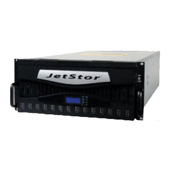
- Page 1 742F Service Manual...
- Page 2 Service Manual Table of Contents Section: Page: 1. How to Replace the RAID Controller (ARC8006) ........13 2. How to Replace the Power Supply Fan Module (PSFM) ........23 3. How to Replace the Turbo Fan (Fan 06-1) .......... 28 4.
- Page 3 Service Manual NOTE: When replacing parts, make sure to handle the parts carefully. It is necessary to use anti-static hand gloves or a wrist strap when handling sensitive parts, such as circuit boards or PCBA. Make sure that somebody is around to provide help when needed, such as when moving the whole enclosure.
- Page 4 Service Manual IMPORTANT: (1.) When the subsystem is online and a Power Supply fails, and the replacement Power Supply module is not yet available, don’t remove or disconnect the failed Power Supply module. This is to maintain proper airflow within the enclosure, since the fans will still be working.
- Page 5 Service Manual Dual Controller RAID Subsystem NOTE: Each Power Supply Fan Module has 1 Power Supply and 5 Fans. For the purpose of hardware monitoring, the RAID enclosure is logically divided into two enclosures. The functions of the Expander Modules are as follows: Module: Function/Description: Monitors Enclosure 1 (Disk slots 1 to...
- Page 6 Service Manual Before servicing the RAID subsystem, please see the following table for additional information about specific problem and what to replace. Problem What to do / What to Replace 1. Check first if the LCD cable is properly connected to the LED front panel module and LCD display module.
- Page 7 Service Manual Problem What to do / What to Replace 1. Check first if the RAID controller(s) can start-up normally (not hang). If controller(s) cannot boot-up normally, check the RAID controller(s). 2. Make sure all expander modules are working fine. If there is a failed expander module, check or replace it first.
- Page 8 Service Manual Problem What to do / What to Replace 1. Check the cable of Switch Mechanism in both RAID controllers, if cable is properly connected. Refer to Section 4 Step D. 2. To verify if the 2 RAID controllers are working fine, power off the enclosure, disconnect the cable of Switch Mechanism in both RAID controllers, and then power...
- Page 9 Service Manual Problem What to do / What to Replace 1. Check the cable of Switch Mechanism in the faulty RAID controller, if cable is properly connected to the RAID controller. Refer to Section 4 Step D. 2. Remove and reinsert the RAM module (cache memory) in the faulty RAID One RAID controller does not controller.
- Page 10 Service Manual Problem What to do / What to Replace 1. Make sure that the power cords are connected to the 2 PSFM (Power Supply fan Module), and that the power on switch of the 2 PSFM are turned on. Verify that the Power Status LED becomes red when the power cable is inserted in the AC input power socket.
- Page 11 Service Manual Problem What to do / What to Replace 1. Make sure the disk drive (SATA or SAS) is good. Verify that the Power On/Fail LED is green (good). If LED is red, try the disk drive in another disk slot. 2.
- Page 12 Service Manual Problem What to do / What to Replace 1. Check fan cable inside the Turbo Fan, if properly connected. Refer to Section 11 step The Turbo Fan (Fan 06-1) is failed. The Hardware 2. Try to replace the Fan Board, or replace the Monitor shows the Fan Turbo Fan.
- Page 13 Service Manual 1. How to Replace the RAID Controller (ARC8006) A. When a RAID controller fails, the FLT LED will be blinking red indicating controller failure Shutdown the Raid System. Loosen the thumbscrews on the sides of the failed RAID controller. Loosen the 2 thumbscrews on both sides of the failed controller.
- Page 14 Service Manual C. Pull the handle bar of the controller drawer about 90°, and then remove the controller drawer from the slot. (NOTE: The picture is not from actual machine model but from similar RAID series) JetStor SAS 742F...
- Page 15 Service Manual S. Insert the controller drawer into the controller slot. The FLT LED will still blinking red. NOTE: Don’t tighten yet the 2 thumbscrews. The replacement Controller is inserted (NOTE: The picture is not from actual machine model but from similar RAID series) JetStor SAS 742F...
- Page 16 Service Manual T. Reconnect all cables. All cables on the replacement Controller are reconnected / reinserted. (NOTE: The picture is not from actual machine model but from similar RAID series) U. Press the handle bar towards the side of the controller drawer and make sure the handle bar is well attached to the controller drawer side.
- Page 17 Service Manual IMPORTANT: The thumbscrews must be properly tightened so that the FLT LED will be off and the controller status will become After the inserted controller has taken over the original IO jobs of the failed controller, the alarm sound will be off. B controllers will be back to normal operational mode.
- Page 18 Service Manual 2. How to Replace the Power Supply Fan Module (PSFM) NOTE: Each Power Supply Fan Module (PSFM) has one Power Supply and five Fans. PSFM 1 has Power 01-1, Fan 01-1, Fan 02-1, Fan 03-1, Fan 04-1, and Fan 05-1, and PSFM 2 has Power 01-2, Fan 01-2, Fan 02-2, Fan 03-2, Fan 04-2, and Fan 05-2.
- Page 19 Service Manual Power 01-1 and Fan 01-1 to 05-1 NOTE: Fan 06-1 is included in fans being monitored in Enclosure #1 JetStor SAS 742F...
- Page 20 Service Manual Power 01-2 and Fan 01-2 to 05-2 IMPORTANT: When the Power Supply of a PSFM fails, the PSFM need not be removed from the slot if replacement is not yet available. The fans will still work and provide necessary airflow inside the enclosure. After replacing the Power Supply Fan Module and turning on the Power On/Off Switch of the PSFM, the Power Supply will not power on immediately.
- Page 21 Service Manual A. Loosen the thumbscrews of the Power Supply Fan Module. B. Pull the handle of the Power Supply Fan Module. The Power Supply Fan Module will move out from the slot. C. Prepare the new Power Supply Fan Module. JetStor SAS 742F...
- Page 22 Service Manual D. Insert the replacement Power Supply Fan Module and push inwards. With the handle in open position, close the handle until the lock is engaged. E. Tighten the 2 thumbscrews of the PSFM. F. Reconnect the power cable. Turn on the PSFM power switch. JetStor SAS 742F...
- Page 23 Service Manual 3. How to Replace the Turbo Fan (Fan 06-1) JetStor SAS 742F...
- Page 24 Service Manual A. Loosen the 2 screws of the Turbo Fan module. B. Pull the handle to remove the Turbo Fan module from the slot. C. Insert the replacement Turbo Fan module. Fan Board Turbo Fan Fan Cable NOTE: If only the fan board will be replaced, disconnect first the fan cable, loosen the screws on the fan board, and replace the fan board.
- Page 25 Service Manual D. Insert and push the Turbo Fan module until it is fully inserted. E. Tighten the 2 screws of the Turbo Fan module. JetStor SAS 742F...
- Page 26 JetStor SAS 742FD RAID Subsystem 2.6 Disk Tray The Disk Tray houses a 3.5 inch hard disk drive. It is designed for maximum airflow and incorporates a carrier locking mechanism to prevent unauthorized access to the HDD. Key for Disk Tray Lock User Manual...
- Page 27 JetStor SAS 742FD RAID Subsystem 2.6.1 Disk Drive Installation This section describes the physical locations of the hard drives supported by the subsystem and give instructions on installing a hard drive. The subsystem supports hot-swapping allowing you to install or replace a hard drive while the subsystem is running.
- Page 28 JetStor SAS 742FD RAID Subsystem IMPORTANT: In dual controller mode, the installation of SATA disk drive in a disk tray is done differently. In single controller mode, the installation of SATA disk in a disk tray is the same with SAS disk. Single Controller Dual Controller SATA...
- Page 29 JetStor SAS 742FD RAID Subsystem 3. Connect the dongle board into the SATA disk drive. 4. Place the SATA disk drive into the disk tray, then turn the disk tray upside down. To secure the disk drive into the disk tray, tighten 4 screws on the holes of the disk tray.
- Page 30 JetStor SAS 742FD RAID Subsystem To install a SAS disk drive (Single or Dual Controller Mode) or SATA disk drive (Single Controller Mode) in a disk tray: 1. Use the Key for Disk Tray Lock to unlock a disk tray. 2.
- Page 31 JetStor SAS 742FD RAID Subsystem To install the disk trays into the disk slots: Loosen two screws on both sides of the top cover on the front panel side. b. Use the Top Cover Key to unlock the key lock on the front panel side. c.
- Page 32 JetStor SAS 742FD RAID Subsystem d. Insert each disk tray with disk drive one by one, 14 disk trays or one row first, and then lock each disk tray. Then do the same for the next 14 disk trays or row.
- Page 33 JetStor SAS 742FD RAID Subsystem e. When all disk trays have been installed and locked, put the top cover back and place it about half an inch away. Then push the top cover towards the rear. f. Use the Top Cover Key to lock the key lock on the front panel side. g.
Need help?
Do you have a question about the JetStor 742F and is the answer not in the manual?
Questions and answers