Table of Contents
Advertisement
Quick Links
Advertisement
Table of Contents

Subscribe to Our Youtube Channel
Related Manuals for FLIGHT LINE FL-760A

Summary of Contents for FLIGHT LINE FL-760A
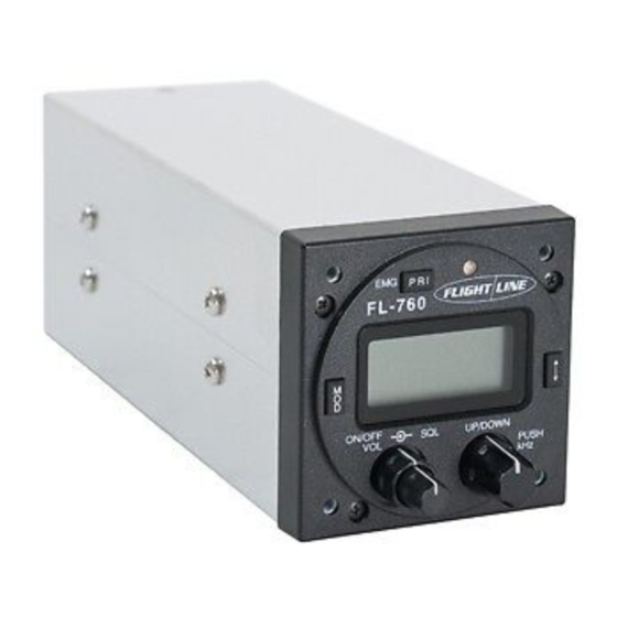
- Page 1 FL-760A VHF Aircraft Transceiver Installation / Operations Manual FL-760 series Flightline 12830 E. Mirabeau Parkway Spokane Valley, WA 99216 Toll free tel.: 1-800-235-3300 Toll free fax: 1-800-828-0623 http:// www.edmo.com VHF AM Aircraft Radio FCC ID: VOSFL760 B Page 0...
-
Page 2: Attention- Read Me First
AT T E N T I O N READ ME FIRST FCC WARNING Changes or modifications not expressly approved by the party responsible for compliance could void the user’s authority to operate the equipment. NOTICE This equipment has been tested and found to comply with the limits for a Class A digital device, pursuant to part 15 of the FCC Rules. -
Page 3: Table Of Contents
TABLE OF CONTENTS SECTION Page ATTENTION- READ ME FIRST ………………………………………………….1 TA B L E O F C O N T E N T S … … … … … … … … … … … … … … … … … … … … … … … 2 1 IN TRODU CTION ……………………………………………………………….. -
Page 4: Introduction
1 INTRODUCTION Thank you for purchasing this quality product from Flightline. This transceiver has been designed and manufactured in Japan specifically for Ultralights, Gliders and General Aviation Aircraft and Helicopters with size and power consumption as the main considerations. Ease of operation was another primary achievement. Please follow this manual closely to ensure optimum performance, we do hope you have many hours of trouble free communication and safe flying. -
Page 5: E N E R A L
The following section is a guide for individual types of aircraft installations. 4.1 Sailplanes Due to the inherent space restriction on most glider instrument panels the FL-760A’s 57-mm front panel makes it an excellent choice for confined spaces. Generally the radio is mounted at the bottom of the panel with essential instruments at the top. -
Page 6: Before Beginning Installation
The following section describes the proper installation and removal of the FL-760A transceiver. 5.3 General The following information is provided as a guide for installation in uncertified aircraft. If the FL-760A is to be installed in a certificated aircraft, the installation must be done by a certified repair station. 5.4 Pin connections Pin No. -
Page 7: Electrical Installation
14-volt or 28-volt source. It is advisable to run this via a circuit breaker or fuse (2-amp max). NOTE- The FL-760A has an internal 10 amp fusible link which is not field replaceable. If the radio fails it must be returned to a Flightline approved repair facility. -
Page 8: Antenna Installation
For Motor Glider and Ultralights install the following intercom switch wiring. Wire the center conductor to PIN 5 and the shield to ground. The switch is the same as for the backlight switch described previously or when the switch is not used, you can use voice operation (VOX function). -
Page 9: Operation Of Equipment
6 OPERATION OF EQUIPMENT 6.1 General Please read this section for the correct description and operation of this equipment. 6.2 Control Description Following diagram shows the position of the controls. ④ ⑤ ⑥ ⑦ ① ② ③ ① Volume and On/Off control Turn fully anticlockwise to switch off. - Page 10 Press and hold this key for two seconds to activate the emergency frequency. If the external memory button is pushed after the priority memory is called, it becomes a priority scan. ⑤ LED Indicator ・ A clear display indicates a muted receive condition. ・...
-
Page 11: Memory Programming
⑦ External memory toggle This button alternately replaces an active frequency and the standby frequency. Active Standby 6.3 Memory programming The top line should read memory channel 1 (1 to 99 and PRI). Select the required memory number with the up/down dial. Next push the dial to select the bottom line MHz. -
Page 12: Music Input
・ Audio level of Intercom ① Push the “MOD” button and select the INT. ② Turn on the dial switch and Select the 00 to 80. ③ Push the arrow key, enter the Intercom sensitivity. ・ Time out time of transmit. ①... -
Page 13: Specifications
7 SPECIFICATIONS General b. Frequency range : 118.00 to 136.975MHz (Receive:108.00 to 136.975MHz) c. Channel spacing : 25kHz d. Mode : AM (6K00A3E) e. Number of memory channels : 99 f. Acceptable power supply : 10.5 V to 33 VDC (Negative ground only) g. -
Page 14: Helpful Hints
8 HELPFUL HINTS ・ Installing an inline power filter consisting of an LC network may reduce stubborn ignition noise. These are readily available and are commonly used to suppress noise getting into stereo systems. gg. Use shielded spark plug leads. hh. - Page 15 Certified Aircraft: Any approved VHF communications antenna 6.5mm (1/4") 3.2mm (1/8") 1.6mm (1/16") BNC termination Coaxial cable termination Radio hole cutout dimensions (drawing not to scale) Page 14...
- Page 16 Limited Liability Warranty Flightline warrants this product to be free from defects in materials and workmanship for 1 year from the date of purchase or the minimum period described by applicable consumer law. If the unit is installed by an organization which holds an avionics installation approval from the FAA, and that organization has co-signed and dated the warranty card, the warranty period shall be deemed to commence from the date of installation.
Need help?
Do you have a question about the FL-760A and is the answer not in the manual?
Questions and answers