Table of Contents
Advertisement
Quick Links
Advertisement
Table of Contents

Related Manuals for ARF MODEL Corvus Racer540 30CC V2

Summary of Contents for ARF MODEL Corvus Racer540 30CC V2
- Page 1 ARF MODEL Corvus Racer540 30CC V2 Instruction Manual...
- Page 2 Dear Customer, Thanks for purchasing this newly designed Corvus Racer540 30CC V2 aerobatic RC airplane. The weight is approximately 10Lbs. It’s good for IMAC and free style flying. It’s a beautiful plane with amazing flight performance. It’s covered with genuine monocote, and comes with good quality accessories, including carbon fiber wing tube, Anodized 6061 aluminum landing gear or carbon fiber as an option.
-
Page 3: Specifications
SPECIFICATIONS WING SPAN: 72"(1830mm) LENGTH: 70"(1780mm) WING AREA: 1017sq in(65.6sq dm) FLYING WEIGHT: 9.7-11lbs(4400-5000g) Glow: .91-1.20(2C) 1.10-1.40(4C) Gas: 26CC-38CC Gas DLE30 DLE35 Electric Power: KUZA EXM 5420 185KV with 12S 3300-4000mAh 18x10 prop KUZA EXM 5420 280KV with 8S 3700-4400mAh 18x10 prop DUSKY XM6350EA-12 with 8S 3700-4400mAh 18x10 prop Or other 1800-2000Watt electric motor ESC:80-100A... - Page 4 Air exit opeing behind the rudder servo for electric set-ups Includes Side Force Generator’s(SFG) Canopy extended into cowl...
- Page 5 Quick release canopy latch Full length Tuned pipe tunnel designed into fuselage Anodized aluminum Long servo arms included...
- Page 6 Servo extension safety connector clips High performance cap head screws Flat nylon hinges for better flying strength...
- Page 7 High quality 2.5mm ball links assembly New dual fiberglass horn assembly New Carbon fiber tail wheel assembly...
- Page 8 High-quality durable rubber wheels Improved new Axle (the material of Axle is stainless steel ) Two options for landing gear: Anodized 6061 Aluminum or Carbon fiber Carbon fiber landing gear Anodized 6061 Aluminum landing gear...
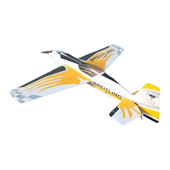
- Page 9 Larger carbon fiber wing tube diameter than V1 Previous versions. Scheme A White/Yellow/Black...
- Page 10 Scheme B Red /White/ Black...
- Page 11 Items Required to Complete This Model: Two switches with charging jacks for the Rx Two high quality Rx batteries of significant capacity to power your choice of servos. 26-38CC Gas engine One Receiver of your choice Motor ...
- Page 12 Be sure you go over all seams and edges of the covering to assure it is secure to the airframe and other covering. Be careful not to apply too much heat or you may cause bubbles or damage to the covering. A heat gun may also be used along with a soft cotton cloth to shrink and adhere the covering.
- Page 13 Pushrods: Two 2.5x60mm Pushrods for aileron. Three 2.5x120mm Pushrods for elevator & rudder (Pull-push style) Pull-pull setup for the rudder. Ball links: 8 for aileron and elevator.
- Page 14 Servo arms: 4 single arms for aileron and elevator. 1 dual arm for rudder. 5 Servo extension safety connector clips Main rubber wheels:2PCS...
- Page 15 New stainless steel Axle kits: 2PCS New Carbon fiber tail wheel assembly. Side force generators (Four 3x14mm Hexagon bolts & 4 Washers) Motor mount for brushless motor...
- Page 16 Engine mount for nitro or gas engine Screews for landing gear: 4(4x20mm) Hexagon bolts & 4mm stainless steel Self-locking nuts & washers Screws for cowl: 4(3x14mm) Hexagon bolts & 4 washers...
-
Page 17: Wing Assembly
4 allen key wrenches Wing Assembly NOTE: There are pictures of different planes in this manual, however, this plane’s wings is assembled the same way. 1. It is much easier to install the twin control horns before installing the wing. Locate the fiberglass aileron control horns, ball links, and associated bolts and nylon-insert lock nuts. - Page 18 6. Now coat the other end of the hinges with epoxy and install the aileron into the trailing edge of the wing. Again, make sure the hinges remain in proper alignment. Using paper towels and some isopropyl alcohol clean off any excess epoxy from the hinges and surrounding areas. 7.
-
Page 19: Elevator Assembly
11. We recommend using KUZA 1.5” aluminium CNC servo arm (sold separately) for wing control. Elevator Assembly NOTE: Some pictures are of different planes in this manual, however, this plane’s elevator is assembled the same way. 1.Cut the covering over the hole for elevator on the fuselage. Glue the elevator to the fuselage. Making sure it’s centered. - Page 20 2. Use two servos for the elevators. 3,Glue the hinge for the elevator the same way as the main wings.
- Page 21 4.Install the horns the same way as the horns on the aileron. Use your radio to set the servo center position and install the large control horn onto the servo. Assemble the control rod and ball links and adjust the control linkage for proper geometry.
-
Page 22: Rudder Assembly
We recommend using KUZA 1.5” aluminium CNC servo arm (sold separately) for wing control. Rudder Assembly 1. Install the fiberglass control horns in the same way as you did the elevator horns. - Page 23 2.The CORVUS is supplied with a high quality set of pull-pull cables and ball-links. 3.Locate the pull-pull cable set, threaded couplers, brass swaging tubes, and ball-links. If the cable is one long piece, cut it into two equal length pieces. Thread one end of the one cable through a brass tube and then through one of the threaded couplers.
- Page 24 6. Check the operation of the rudder using your radio and make sure there is no binding and the cables are adjusted properly. You may have to tighten the cables after a few flights as they may stretch slightly from the initial installation.
- Page 25 8.The CORVUS also provide pull-push style for rudder. Cut off excess fiberglass rudder horn, and use sandpaper to roughen up the parts needed to inlay. Use epoxy glue to glue the rudder horn. Use 2.5X120mm push rod install rudder sliding systems.
-
Page 26: Tail Wheel Installation
9. We recommend using KUZA 1.5” aluminium CNC servo arm (sold separately) for rudder control. Tail Wheel Installation 1. Begin the tail wheel assembly by installing the hollow hex bolt and lock nut into the large hole at the rear of the tail wheel bracket. - Page 27 2. Slide 3 wheel collars and the wheel onto the pre-bent tail wheel wire and tighten in place with thread lock as shown below. 3.Install steering rod, again, the use of thread-lock on any metal to metal screw is advised.
- Page 28 4.There are 3 pre-installed blind nuts on the rear of the fuselage, locate the screw holes and puncture the covering. Then install the CF tail wheel bracket with M3X16 self-threaded screw. 5.Drill a screw hole on the bottom of rudder, 190-210 mm away from the hinge line, with 2 mm drill bit. Secure one end of the wheel spring with a M3X12mm self-threaded screw, then hook the other end onto the steering rod.
-
Page 29: Main Landing Gear Installation
6.Fully installed tail wheel assembly is shown below. Main Landing Gear Installation NOTE: There are pictures of different planes in this manual, however, this plane’s landing gear is assembled the same way. 1. Locate the 2 fiberglass landing gear fairings and the black silicone tubing. Cut through one wall of the tubing along the length. - Page 30 2. Bolt the main gear to the bottom of the fuselage using the supplied screws and stainless steel Self-locking nuts. Place the bolts in through the can tunnel opening with appropriate size spanner. Remember the gear will rake forward. 3. Adjust the position of the landing gear fairings, the secure with glue (shoe goo type).
- Page 31 4. Install the wheel axles to the landing gear and tighten the nylon-insert lock nut. Install one wheel collar onto the axle. Use a second wheel collar as a guide to leave a gap on the inboard of the axle. Use a small drop of thread-lock and tighten in place.
-
Page 32: Engine Installation
5.Fit the wheel pant in place and install using the two supplied screws. Use thread-lock to secure the screws in place. Repeat the above steps for the other main gear. ENGINE(Motor), EXHAUST, & FUEL SYSTEM ENGINE Installation NOTE: There are pictures of different planes in this manual, however, this plane’s engine is assembled the same way. - Page 33 2. Fit the Cowl and measure the distance from the engine bulkhead to the front of the cowl, add approx 2-3mm for the back plate and this is the length that your engine should be set Using the correct length stand offs, mount your engine securely using bolts, washers, and locknuts.
- Page 34 5. Assemble the throttle servo mount using the supplied laser cut parts or there is a servo cutout in the bottom of the engine box for 28cc-38cc engines. Mount your throttle servo and complete your linkage setup. A hole will need to be drilled on the firewall to allow the pushrod to connect to the throttle arm on the carb.
-
Page 35: Motor Installation
side opposite your ignition switch. Make sure your vent line does not come close to any hot exhaust part such as the muffler or canister. recommends the use of small zip ties or fuel line clamps to secure the lines to the tank. -
Page 36: Cowling Installation
3.First install the motor mount on the firewall. Then install the motor. Adjust the motor mount to fit the cowl. 4. After adjusting the motor mount to the right position, lock the 4 screews, unscreew them, apply 30-minute epoxy, and tighten the screws to the previously-found position. 5. - Page 37 1. The cowl is secured with four 3 X 14mm bolts and washers.Apply nutlock onto the bolts as the vibration from the gas engine will shake them come loose. 2. Labels are provided for aligning the drill holes for the cowl. Stick then on without the cowl, mark the hole.
- Page 38 2. Mount your reciever(s) securely in a location which provides a clean and maintenance free solution to your setup. All servo wires should be neatly routed and secured in place so they will not come loose or flop around during flight. 3.
- Page 39 Recommended control surface deflections: Low Rate High Rate Elevator 15 degrees 45-50 degrees Rudder 25 degrees 40-45 degrees Ailerons 25 degrees 35-40 degrees FINAL ASSEMBLY AND PRE-FLIGHT INSPECTIONS 1. Before arriving at your flying field, be sure all your batteries are properly charged and all radio systems are in proper working order.
- Page 40 4. Fill your fuel tank making sure your vent line is not plugged or capped. With the canopy off, this is a good time to check for any fuel leaks. 5. Position the canopy in place and tighten the ALU Canopy Bolts. Be sure to use the supplied rubber washers under the screw heads.
- Page 41 For Hitec servo(24T): 39mm/1.5in Single No. KAG0S72H 84mm/3.25in Dual No. KAG0D72H For JR servo(23T): 39mm/1.5in Single No. KAG0S72J 84mm/3.25in Dual No. KAG0D72J...
- Page 42 * KUZA new Wingbag for 30CC Two color to choose: red/ black, blue / silver KAG0093 *3in C.F Spinner with Alu base ( for electric) No. KAG0126 *3in C.F spinner for Nitro&Gas No. KAG0134...
- Page 43 *3in Nylon Spinner No. KAG0187 *3in Nylon Spinner with Aluminium Backplate No. KAG0197...
Need help?
Do you have a question about the Corvus Racer540 30CC V2 and is the answer not in the manual?
Questions and answers